- EN 10305-4
- China
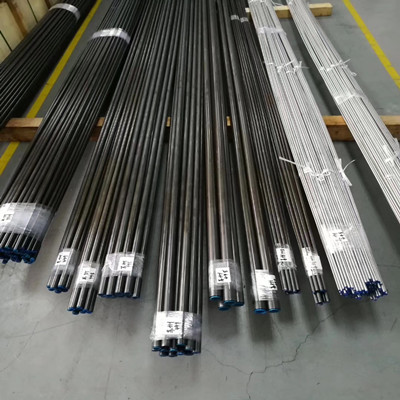
- Stock
- E215,E235,E355
EN 10305-4 E355 Precision Seamless Cold Drawn Tubes for hydraulic and pneumatic power systems.EN 10305-4 Steel tubes for precision applications - Technical delivery conditions - Part 4: Seamless cold drawn tubes for hydraulic and pneumatic power syste
EN 10305-4 E355 Precision Seamless Cold Drawn Tubes
EN 10305-4 E355 Precision Seamless cold drawn tubes
EN 10305-4 E215, E235, E355 Seamless cold drawn tubes for hydraulic and pneumatic power systems
Standard:EN 10305-4
EN 10305-4 Steel tubes for precision applications - Technical delivery conditions - Part 4: Seamless cold drawn tubes for hydraulic and pneumatic power systems.
Tubes are characterized by having precisely defined tolerances on dimensions and a specified maximum surface roughness.
Manufacturing process
Steels shall be fully killed.
Tube manufacture and delivery conditions
The tubes shall be manufactured from hot finished seamless hollows by cold drawing.
The tubes shall be delivered in the delivery condition +N which means that after the final cold drawing operation the tubes are normalized in a controlled atmosphere.
Chemical composition of EN 10305-4 E355 Precision Seamless Cold Drawn Tubes
| Steel grade | % by mass | ||||||
| Steel name | Steel number |
C max. |
Si max. |
Mn max. |
P max. |
S a max. |
Al total b min. |
| E215 | 1.0212 | 0,10 | 0,05 | 0,70 | 0,025 | 0,025 | 0,025 |
| E235 | 1.0308 | 0,17 | 0,35 | 1,20 | 0,025 | 0,025 | 0,015 |
| E355 | 1.0580 | 0,22 | 0,55 | 1,60 | 0,025 | 0,025 | 0,020 |
| Elements not quoted in this table (but see footnote b ) shall not be intentionally added to the steel without the agreement of the purchaser, except for elements which may be added for the purposes of deoxidation and/or nitrogen binding. All appropriate measures shall be taken to prevent the addition of undesirable elements from scrap or other materials used in the steel making process. | |||||||
| a This requirement is not applicable provided the steel contains a sufficient amount of other nitrogen binding elements, such as Ti, Nb or V. If added, the content of these elements shall be reported in the inspection document.When using titanium, the manufacturer shall verify that (Al + Ti/2) ≥ 0,020. | |||||||
Table 2 specifies the permissible deviations of product analysis from the specified limits on cast analysis given in Table 1.
Table 2 — Permissible deviations of the product analysis from the specified limits on the cast analysis given in Table 1
| Element |
Specified limit of the cast Analysis , % by mass |
Permissible deviation of the product analysis, % by mass |
| C | ≤ 0,22 | + 0,02 |
| Si | ≤ 0,55 | + 0,05 |
| Mn | ≤ 1,60 | + 0,10 |
| P | ≤ 0,025 | + 0,005 |
| S | ≤ 0,015 | + 0,003 |
| Al | ≥ 0,015 | - 0,005 |
Mechanical properties of EN 10305-4 E355 Precision Seamless Cold Drawn Tubes
| Steel grade |
Yield strength a R eH min.MPa |
Tensile strength R m MPa |
Elongation after Fracture A min.% |
|
| Steel name | Steel number | |||
| E215 | 1.0212 | 215 | 290 to 430 | 30 |
| E235 | 1.0308 | 235 | 340 to 480 | 25 |
| E355 | 1.0580 | 355 | 490 to 630 | 22 |
| The steel grades defined in this document have an intrinsic minimum transverse impact energy of 27 J at 0 °C. | ||||
| a For tubes with outside diameter D ≤ 30 mm and wall thickness T ≤ 3 mm, the R eH minimum values are 10 MPa lower than the values given in this table. | ||||
Appearance and soundness
The tubes shall have smooth outer and inner surfaces with a roughness Ra ≤ 4 μm,
NOTE In the case of the inner surface, this requirement applies to inside diameters ≥ 15 mm.
Dimensions and tolerances
|
Specified outside diameter D with tolerance a |
Specified inside diameter d with tolerance a |
Specified wall thickness T with tolerance a | |||
| 4 | ±0,08 | 3 | ±0,15 | 0,5 | ±0,10 |
| 2 | 1 | ±0,10 | |||
| 5 | ±0,08 | 3,5 | ±0,15 | 0,75 | ±0,10 |
| 3 | 1 | ±0,10 | |||
|
6 |
±0,08 | 4 | ±0,12 | 1 | ±0,10 |
| 3 | ±0,15 | 1,5 | ±0,15 | ||
| 2 | 2 | ±0,20 | |||
| 8 | ±0,08 | 6 | ±0,10 | 1 | ±0,10 |
| 5 | 1,5 | ±0,15 | |||
| 4 | ±0,15 | 2 | ±0,20 | ||
| 3 | 2,5 | ±0,25 | |||
| 10 | ±0,08 | 8 | ±0,08 | 1 | ±0,10 |
| 7 | ±0,12 | 1,5 | ±0,15 | ||
| 6 | ±0,15 | 2 | ±0,20 | ||
| 5 | 2,5 | ±0,25 | |||
| 12 | ±0,08 | 10 | ±0,08 | 1 | ±0,10 |
| 9 | ±0,10 | 1,5 | ±0,15 | ||
| 8 | ±0,12 | 2 | ±0,20 | ||
| 7 | ±0,15 | 2,5 | ±0,25 | ||
| 6 | 3 | ±0,30 | |||
| 14 | ±0,08 | 12 | ±0,08 | 1 | ±0,10 |
| 11 | 1,5 | ±0,15 | |||
| 10 | ±0,10 | 2 | ±0,20 | ||
| 9 | ±0,12 | 2,5 | ±0,25 | ||
| 8 | ±0,15 | 3 | ±0,30 | ||
|
15 |
±0,08 | 13 | ±0,08 | 1 | ±0,10 |
| 12 | 1,5 | ±0,15 | |||
| 11 | ±0,10 | 2 | ±0,20 | ||
| 10 | ±0,12 | 2,5 | ±0,25 | ||
| 9 | ±0,15 | 3 | ±0,30 | ||
| 16 | ±0,08 | 14 | ±0,08 | 1 | ±0,10 |
| 13 | 1,5 | ±0,15 | |||
| 12 | ±0,10 | 2 | ±0,20 | ||
| 11 | ±0,12 | 2,5 | ±0,25 | ||
| 10 | ±0,15 | 3 | ±0,30 | ||
|
18 |
±0,08 | 16 | ±0,08 | 1 | ±0,10 |
| 15 | 1,5 | ±0,15 | |||
| 14 | 2 | ±0,20 | |||
| 13 | ±0,15 | 2,5 | ±0,25 | ||
| 12 | 3 | ±0,30 | |||
| 20 | ±0,08 | 17 | ±0,08 | 1,5 | ±0,15 |
| 16 | 2 | ±0,20 | |||
| 15 | ±0,15 | 2,5 | ±0,25 | ||
| 14 | 3 | ±0,30 | |||
| 13 | 3,5 | ±0,35 | |||
| 12 | 4 | ±0,40 | |||
| 22 | ±0,08 | 20 | ±0,08 | 1 | ±0,10 |
| 19 | 1,5 | ±0,15 | |||
| 18 | 2 | ±0,20 | |||
| 17 | 2,5 | ±0,25 | |||
| 16 | ±0,15 | 3 | ±0,30 | ||
| 15 | 3.5 | ±0,35 | |||
| 14 | 4 | ±0,40 | |||
| 25 | ±0,08 | 22 | ±0,08 | 1,5 | ±0,15 |
| 21 | 2 | ±0,20 | |||
| 20 | 2,5 | ±0,25 | |||
| 19 | ±0,15 | 3 | ±0,30 | ||
| 17 | 4 | ±0,40 | |||
| 16 | 4.5 | ±0,45 | |||
| 15 | 5 | ±0,50 | |||
| 28 | ±0,08 | 25 | ±0,08 | 1,5 | ±0,15 |
| 24 | 2 | ±0,20 | |||
| 23 | 2,5 | ±0,25 | |||
| 22 | ±0,15 | 3 | ±0,30 | ||
| 20 | 4 | ±0,40 | |||
| 18 | 5 | ±0,50 | |||
| 30 | ±0,08 | 26 | ±0,08 | 2 | ±0,20 |
| 25 | 2,5 | ±0,25 | |||
| 24 | ±0,15 | 3 | ±0,30 | ||
| 22 | 4 | ±0,40 | |||
| 20 | 5 | ±0,50 | |||
| 18 | 6 | ±0,60 | |||
| 35 | ±0,15 | 31 | ±0,15 | 2 | ±0,20 |
| 30 | 2,5 | ±0,25 | |||
| 29 | 3 | ±0,30 | |||
| 27 | 4 | ±0,40 | |||
| 25 | 5 | ±0,50 | |||
| 23 | 6 | ±0,60 | |||
| 38 | ±0,15 | 34 | ±0,15 | 2 | ±0,20 |
| 33 | 2,5 | ±0,25 | |||
| 32 | 3 | ±0,30 | |||
| 30 | 4 | ±0,40 | |||
| 28 | 5 | ±0,50 | |||
| 26 | 6 | ±0,60 | |||
| 24 | 7 | ±0,70 | |||
| 22 | 8 | ±0,80 | |||
| 42 | ±0,20 | 38 | ±0,20 | 2 | ±0,20 |
| 36 | 3 | ±0,30 | |||
| 34 | 4 | ±0,40 | |||
| 32 | 5 | ±0,50 | |||
| 30 | 6 | ±0,60 | |||
| 26 | 8 | ±0,80 | |||
| 50 | ±0,20 | 42 | ±0,20 | 4 | ±0,40 |
| 40 | 5 | ±0,50 | |||
| 38 | 6 | ±0,60 | |||
| 34 | 8 | ±0,80 | |||
| 32 | 9 | ±0,90 | |||
| 30 | 10 | ±1,00 | |||
| 55 |
±0,25 |
47 | ±0,25 | 4 | ±0,40 |
| 43 | 6 | ±0,60 | |||
| 39 | 8 | ±0,80 | |||
| 35 | 10 | ±1,00 | |||
| 60 | ±0,25 | 50 | ±0,25 | 5 | ±0,50 |
| 44 | 8 | ±0,80 | |||
| 40 | 10 | ±1,00 | |||
| 35 | 12.5 | ±1,25 | |||
| 70 | ±0,30 | 60 | ±0,30 | 5 | ±0,50 |
| 54 | 8 | ±0,80 | |||
| 50 | 10 | ±1,00 | |||
| 45 | 12.5 | ±1,25 | |||
| 80 | ±0,35 | 68 | ±0,35 | 6 | ±0,60 |
| 64 | 8 | ±0,80 | |||
| 60 | 10 | ±1,00 | |||
| 55 | 12.5 | ±1,25 | |||
| a Dimensions and tolerances only apply for the ordered pair of dimensions | |||||
The tubes shall be delivered with square cut ends. The ends shall be free from harmful burrs.
NOTE For outside diameters D < 8 mm or inside diameters d < 4 mm, the tubes may have deformed ends.
Inspection and testing
Chemical analysis
Tensile test
Drift expanding test
Dimensional inspection
Non-destructive testing
Visual examination
NDT for verification of leak tightness
Roughness measurement
NDT on longitudinal imperfections
Marking
The following marking shall be applied indelibly on each tube. The marking shall be repeated continuously along a line parallel to the tube axis, with a maximum interval of 1,5 m between two sequences, 5 % of the tubes may contain only one mark.
The marking shall include the following information:
— the manufacturer’s name or trade mark;
— the specified dimensions;
— the number of this Standard;
— the steel name;
— in the case of specific inspection, an identification number (e.g.

Product key description, this is a very good product description, detailing our product use, product characteristics