JIS G3460 Steel tubes for low temperature service
JIS G3460
Steel tubes for low temperature service
1 Scope
This standard specifies the steel pipe for piping used at particularly low temperature below freezing (hereinafter referred to as pipe).
This standard usually applies to pipes with an outer diameter of 10.5 mm (nominal diameter 6A or 81B) to 660.4 mm (nominal diameter 650A or 26B).
In addition to the items specified in the main body, Annex JA specifies items of special quality specifications that can be specified by the orderer in advance by agreement with the manufacturer.
NOTE 1 Austenitic stainless steel pipes specified in JIS G 3459 and JIS G 3468 can be used as low-temperature pipes.
NOTE 2 The following shows the corresponding international standard of this standard and the symbol indicating its degree of correspondence.
ISO 9329-3: 1997, Seamless steel tubes for pressure purpose-Technical delivery conditions-Part 3: Unalloyed and alloyed steel with specified low temperature properties
ISO 9330-3: 1997, Welded steel tubes for pressure purposes-Technical delivery conditions-Part 3: Electric resistance and induction welded unalloyed and alloyed steel tubes with specified low temperature properties (overall evaluation: MOD)
Note that the symbol MOD that indicates the degree of correspondence indicates that correction is made based on ISO / IEC Guide 21-1.
2.Referenced Documents
The specifications listed below form part of the specifications by referring to this specification. These citation specifications are the latest editions (including supplements). Application.
JIS G 0320: Analysis Method of Steel Mel
JIS G 0321: Product Analysis Method of Steel and Its Permissible Variation Value
JIS G 0404: General Delivery Conditions for Steel
JIS G 0415: Steel and Steel Products - Inspection Documents Notes Corresponding to International Standards: ISO 10474, Steel and Steel Products - Inspection Documents (IDT)
JIS G 0582: Automatic Ultrasound Inspection Method for Steel Pipe
JIS G 0583: Automatic Eddy Current Inspection Method for Steel Pipe
JIS Z 2241: Tensile Test Method for Metal Materials
JIS z2242: Charpy impact test method for metallic materials
JIS Z 8401: Rounding Numbers
3.Grade and Designation
There are three types of tubes, and their classification, symbols for types and symbols for manufacturing methods are as per Table 1.
Table 1-Classification, Classification symbols and symbols representing manufacturing methods
4 Manufacturing method
The manufacturing method is as follows.
a) The tube is made of fine-grained killed steel, STPL 380 is manufactured seamlessly or by electrical resistance welding, and STPL 450 and STPL 690 are manufactured seamlessly.
b) The pipe is heat-treated in Table 2. However, when performing heat treatments other than those in Table 2, it is based on the agreement between the delivery parties. Cold-finished tubes are heat-treated after cold-finishing.
Table 2-Heat treatment
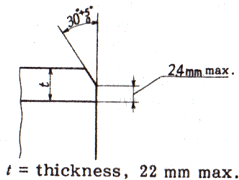
c) The end of the pipe is plain end unless otherwise specified. If the orderer specifies a bevel end, the shape shall be in accordance with the agreement between the delivering and receiving parties, in particular when no shape is specified, according to Figure 1.
5 Chemical constituents
The pipe is tested according to 10.1, and its molten steel analysis values are as per Table 3. When performing product analysis according to the request of the orderer, the test is performed according to 10.1, and the product analysis value is the value of Table 3. The allowable variation value is the seamless steel pipe of STPL 380, Table 3 of JIS G 0321, electrical resistance For welded steel pipes, see Table 2 of JIS G 0321. For STPL 450 and STPL 690 tubes, see Table 4 in JIS G 0321.
Table 3-Chemical composition
If necessary, alloying elements not listed in this table may be added.
Note a) For STPL 380, 0.010% or more acid-soluble aluminum shall be included if the impact test is not carried out in accordance with 6.4 c). Instead of acid-soluble aluminum, total aluminum may be analyzed, and the content in this case is 0.015% or more.
6 Mechanical properties
6.1 Tensile strength, yield point or yield strength, and elongation
The pipe is tested according to 10.2.3, and its tensile strength, yield point or resistance, and elongation are as per Table 4. However, when a tensile test is performed using No. 12 test pieces or No. 5 test pieces in a tube with a thickness of less than 8 mm, the minimum value of elongation is as shown in Table 4 for each reduction of thickness by 1 mm. The value obtained by subtracting 1.5 from the value shall be rounded to an integer value according to Rule A of JIS Z 8401.
Table 4-Tensile strength, yield point or yield strength, and elongation
Note 1N / mm2 = 1 MPa
Note) For tubes with an outside diameter of less than 40 mm, the elongation in this table does not apply, but the results of the test are recorded. However, the growth may be regulated by an agreement between the delivery parties.
Table 5-Minimum elongation values for No. 12 specimens (in the axial direction) and No. 5 specimens (in the direction perpendicular to the tube axis) of pipes less than 8 mm thick
6.2 Flattening Resistance
Tubes shall be tested according to 10.2.4 and shall not crack the specimens. In this case, the distance between the flat plates is given by equation (1).

Where H: distance between flattening plates(mm)
t: wall thickness of pipe(mm)
D: outside diameter of pipe(mm)
e: constant, 0.08
The orderer may specify bendability instead of flat for pipes with an outer diameter of 50 mm or less.
NOTE See 10.2.4 for the implementation of the test for flatness.
6.3 bending
When the bending property is specified instead of the flatness for the tube of outside diameter of 50 mm, the bending property should be tested by 10.2.5, and cracking is not generated in the test piece. The tube is bent at the inner radius 6 times of the outer diameter and bending angle of 90 °.
Note that the bending angle is an angle from the bending start position.
6.4 absorption energy
The absorbed energy is as follows.
a) the test was carried out by 10.2.6, and the absorbed energy of the Charpy impact test was shown in Table 6. In this case, the test temperature is stpl 380, − 45 ° C., stpl 450 is − 100 ° C., stpl 690 is − 196 ° C. However, if a test is conducted at a temperature lower than these test temperatures by an agreement between the parties to be sent, the test temperature may be substituted for the test.
b) the Charpy impact test of welds is carried out in addition to the Charpy impact test of a), and the absorbed energy is based on table 6. In this case, the test temperature is - 45 ° C. However, if a test is conducted at a temperature lower than this test temperature by an agreement between the parties to be sent, the test temperature may be substituted for the test temperature.
c) the impact test is not carried out in the case of a tube with a size of 10 mm × 5 mm.
Table 6-Absorption energy by Charpy impact test
7 hydraulic test characteristics or non destructive test characteristics
The pipe is tested by 10.3, and the hydrotest or non destructive test characteristics are based on the following. The characteristics are based on the designation of the order. If there is no designation, the manufacturer selects it.
Hydraulic characteristics of hydraulic test characteristics are as follows.
1) when the operator specifies the test pressure, the tube shall be the pressure test lower limit pressure, withstand it, and must not leak. However, if the pressure specified by the orderer exceeds either P or 20 MPa calculated by equation (2), the test pressure is due to an agreement between the parties to be sent. The test pressure to be specified is 0.5 MPa and less than 10 MPa and 1 MPa.

where,
P: Test pressure (MPa)
t: Tube thickness (mm)
D: Outer diameter of tube (mm)
s: 60% (N / mm2) of the specified minimum value of yield point or load resistance in Table 4
2) If the orderer does not specify the test pressure, the tube will withstand this when the hydraulic test lower limit pressure shown in Table 7 is applied, and there shall be no leaks.
In the case of pipes other than those listed in Table 8, calculate the water pressure test lower limit pressure as follows.
2.1) In the case of the outer diameter range in Table 8, select the smaller outer diameter between the outer diameters corresponding to this table.
2.2) If the thickness is within the range of the schedule number of the thickness of the outer diameter selected in 2.1), select the larger thickness among the thicknesses corresponding to this table.
2.3) According to the outer diameter and thickness schedule numbers selected in 2.1) and 2.2), the test is carried out at a pressure higher than the lower limit pressure of the water pressure test in Table 7.
2.4) Water pressure test for pipes other than the dimensions in Table 8 which do not satisfy the conditions of 2.1) and 2.2) The lower limit pressure of the pipe shall be in accordance with the agreement between the delivering parties.
2.5) If the water pressure test lower limit pressure of the schedule No. selected in 2.1) and 2.2) exceeds the test pressure P calculated by equation (1), P instead of the water pressure test lower limit pressure selected in Table 7 Water pressure test Perform the test as the lower limit pressure.
Table 7: hydraulic test pressure ,Unit MPa
b) Nondestructive testing characteristics The tube is subjected to nondestructive testing either ultrasonic testing or eddy current testing, and the nondestructive testing characteristics are as follows. However, it may be replaced with ultrasonic flaw test or eddy current flaw test by agreement between delivery parties, and may be by other nondestructive test specified in Japanese Industrial Standards. The acceptance criteria in this case shall be equal to or greater than those of the ultrasonic flaw test or the eddy current flaw test.
1) Contrast sensitivity classification according to JIS G 0582 or a sensitivity classification stricter than this There shall be no signal that is equal to or greater than the signal from an artificial flaw of the test specimen.
2) Comparison of artificial flaws for flaw detection sensitivity setting according to JIS G 0583 EY or a sensitivity category more severe than that There shall be no signal equal to or greater than the signal from the artificial flaws of the test piece.
8. Scale, mass and dimensional tolerances
8.1 outer diameter, thickness and unit mass
The outer diameter, thickness and unit mass of the tube are shown in Table 8.
Table 8 Dimensions of steel pipes for low temperature service
Note: T=Thickness
8.2 Dimensional Tolerances
The tolerances on outside diameter, wall thickness and deviation in wall thickness of the pipe shall be as specified in Table 8. Further, in the case where the pipe length is specified, the tolerances shall be on the plus side.
Table 9 Tolerances on Outside Diameter, Wall Thickness and Deviation in Wall Thickness
Remarks
1. The tolerances on the outside diameter of the quenched and tempered pipe of STPL 70 shall be【1 % in the case of the hot finished seamless steel pipe 50 mm or over in outside diameter and of the cold finished seamless steel pipe 30mm or over.
2. When the length of circumference is obtained as a basis for tolerances, either the measured value of the length of circumference itself or the diameter derived from the measured value may be used as the criteria.
In either case, the same value (【 0.5 %) shall be applied as the tolerances. The diameter (D) and the length of circumference (l) shall be calculated reversibly from the following
formula
D=I / π
Where π =3.1416
3. In the case where compliance with the tolerances on wall thickness in the above table is clearly confirmed in a local portion such as one under repairs, the tolerances on outside diameter in the above table shall not be applied.
4. The deviation in wall thickness means the ratio of the difference between the maximum and the minimum thickness of the wall measured in the same section to the specified wall thickness, and shall not be applied to the pipe under 5.6mm in wall thickness.
9. Appearance
Appearance is as follows.
a) tube must be practical and straight and both ends are perpendicular to the tube axis.
b) the inner surface of the tube is good in finishing, and there is no defect which is harmful to use.
c) in the case of surface treatment, it may be necessary for grindstone or machining, but the thickness of the product after the care must be within the tolerance of thickness.
d) the ruins must be smoothly formed in the shape of the tube.
10 Testings
10.1 analysis tests
10.1.1 general analysis and analysis sample
The general analysis of the assay and the method for the analysis are taken up by the article 8 (chemical composition) of JIS g 0404. The method of taking the analytic sample when the person requested the product analysis is based on the article 4 of JIS g 0321 (sample sampling method).
10.1.2 analysis methods
The method of analysis of molten steel is based on JIS g 0320. The product analysis method is based on JIS g 0321.
10.2 mechanical testing
10.2.1 general matters of mechanical testing
General conditions of mechanical testing are based on JIS 7 (General requirements) and Article 9 (mechanical property) of JIS g 0404. However, the method of taking the test material to be used for the mechanical test is taken as "a" of JIS g 0404 (test piece sampling condition and test piece).
10.2.2 how to take test materials and number of specimens
The number of specimens to be tested and the number of test pieces are as follows.
A test specimen is collected from 50 pipes per 50 tubes and a fraction of the test pieces of tensile test, flat test or bending test, and the number of specimens is equal to the number of test pieces, and the number of test pieces is taken from each of the 50 tubes and their fractures. A flat test strip is collected. When an order is specified by a tube having an outside diameter of 50 mm or less, one bent test piece is taken instead of the flat test piece.
When a tensile test piece is drawn from an electric resistance welded steel pipe, the test piece 12 or the test piece 5 is collected from the portion without welding.
B) one specimen is collected from each of the 100 tubes and the fractures of each tube of the same size 2 and the simultaneous heat treatment 3), and a set of test pieces (3 pieces) are collected from the respective test materials. In addition to the above Charpy impact test piece, an electric resistance welded steel pipe has a set of Welsh Charpy impact test pieces (3 pieces).
Note that the same size is equal to the same outer diameter.
3) simultaneous heat treatment under continuous heat treatment is good for simultaneous heat treatment in continuous furnace, and it is not included in simultaneous heat treatment when the continuous furnace is stopped.
4) the same heat treatment condition may be used in place of the simultaneous heat treatment in the case where the test material is collected in the same molten steel unit.
10.2.3 tensile test
Tensile test piece and tensile test method are as follows.
(a) the test piece and the specimen sampling direction of JIS z2241, 11, 12a, 12b, 12C, 4 or 5, respectively, are collected from the tube. However, the No.4 test piece is assumed to have a diameter of 14 mm (the target distance is 50 mm). The sampling direction of the test piece is taken from the axial direction of the tube 11 and the specimen 12 in the direction of the tube axis, and the fifth test piece is from the right angle of the tube axis, and the fourth test piece is in the tube axis direction or the right angle of the tube axis. The specimen sampling direction in the case of test piece and test piece to be used depends on the choice of the manufacturer unless otherwise specified.
10.2.4 flattening test
The test piece and test method of the flat test are as follows.
The flat test can be omitted in case of seamless steel pipes, especially without the designation of an order.
Note that the test may be omitted according to the manufacturer's judgment, but that flatness should satisfy the regulation.
a) length of 50 mm or more is cut from the end of the test tube. However, in the case of a tube having an outer diameter of 15% or more, it may be a C shape test piece in which a part of the circumference of the annular specimen is removed.
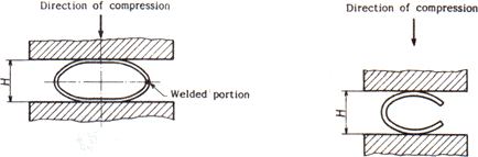
b) the test method specimen is sandwiched between two flat plates under normal temperature, and the distance h between the plates is compressed to below the value of equation (1) of 6.2. However, in the case of an electric resistance welded steel pipe, the welded portion is placed so that the line connecting the center of the tube to the welded portion is perpendicular to the compression direction as shown in Fig. 2. The C-shaped test piece is placed as shown in Fig. 3.
10.2.5 bending test
The test piece and test method of the bending test are as follows.
a) The appropriate length is cut off from the end of the test tube.
b) when the bending angle of the bend, which is defined as 6.3, is set at the upper limit of bending, and the inner radius of bending, which is defined as 6.3, is bent around the cylinder at the inner radius of Examine. In the case of an electric resistance welded steel pipe, the weld is placed at about 90 degrees from the outermost portion of the bending.
10.2.6 Charpy impact test
Test pieces and test methods of the Charpy impact test are as follows.
a) is a V-notch test piece of the test piece and the specimen Z direction. However, the width of the test piece may be changed to 7.5 mm or 5 mm depending on the size of the tube. The sampling direction of the test piece is collected in the direction of the tube axis to the steel piece which does not contain the welded portion of the tube, and the Charpy impact test piece of the welded portion of the electric resistance welded steel pipe is taken in the right direction of the tube axis. Also, if necessary, the surface finishing method of the Charpy impact test piece of the weld portion (for example, the non cutting portion length of the outer circumference of the tube shown in Fig. 4) may be accorded between the parties to be transferred.
The non cutting portion of the Charpy impact test piece is usually carried out within the size range shown in Fig. 4.
The outer circumference of a tube that is not cut
T: test strip width
L: test strip length
Figure 4 - range of non cut portions of Charpy impact test piece
b) Test method According to JIS Z 2242.
10.3 hydraulic or non-destructive testing
Test frequency and test method of the hydraulic test or the non destructive test are as follows.
A frequency hydraulic test or a non destructive test is carried out for each pipe
Test method
1) hydraulic pressure test was conducted on tube
When the pressure exceeds the lower limit pressure of water pressure determined in a) and is held for more than 5 seconds, it withstands and checks whether leakage occurs.
The nondestructive test test method is as follows. However, the test method in the case of other non-destructive testing by the Japanese industrial standard is based on the agreement between the parties.
2.1) ultrasonic testing method is based on JIS g 082. However, the test may be carried out in a range which is more severe than the artificial debris division UD.
2.2) eddy current testing method is based on JIS g 0583. However, the test may be carried out in a strict manner than the artificial shear partition ey.
11 inspection and inspection
11.1 inspection
The inspection is as follows.
a)The general inspection is based on JIS g 0404.
b) the chemical composition must conform to the article 5.
c) the mechanical properties must conform to the article 6.
d) hydraulic test characteristics or non destructive test characteristics must conform to Article 7.
e) the dimension must conform to Article 8.
f) the appearance must conform to Article 9.
g) in the case where some or all of the items of the special quality regulation prescribed in Annex JA are applied pursuant to the agreement between the parties to be sent, it shall conform to the applicable provisions.
11.2 re inspection
The reinspection is as follows.
a) the tube which has not passed in the tensile test, flat test or bending test may re test 9.8 (re test) of JIS g 0404 to determine whether or not it is acceptable.
b) among the tubes which are not suitable for the Charpy impact test, when the average value of the absorbed energy satisfies the regulation and conforms to the following conditions, the test can be carried out to determine whether the test is acceptable.
1) when two values are above the average value of the three specimens in Table 6, and only one value does not satisfy the values of individual specimens in table
2) when two values satisfy the average values of the three specimens in Table 6, but satisfy the values of individual specimens in table
Retests are carried out in a set of (3) specimens newly sampled from the same test material, and each of the three values must conform to the set of average values of the set of table 6.
12 Marking
In the tube which passed the inspection, the following matters must be displayed for each tube. However, if there is a demand for a tube having a small outer diameter and an order of an order, this may be bundled and displayed in an appropriate manner for every bundle. Display order is not specified. When an order of approval is obtained, a part thereof may be omitted.
a) type of symbol
b) a symbol representing a manufacturing method
The symbols representing the manufacturing method are as follows. However,-may be blank.
1) Hot finish seamless steel pipe -S-H
2) Cold finish seamless steel pipe -S-C
3) Electric resistance welded as-is steel pipe -E-G
4) Hot finish electric resistance welded steel pipe -E-H
5) Cold finish electric resistance welded steel pipe -EC
c) Dimensions. The dimensions indicate the nominal diameter and nominal thickness, or the outer diameter and thickness.
Example 50A × Sch40 or 60.5 × 3.9
d) Manufacturer name or its code
e) Symbol Z representing designation of special quality regulations (when designated)
13 Report
Manufacturers must submit inspection documents to the order unless otherwise specified. The report is based on Article 13 (JIS) of JIS g 0404. If the specification of the inspection document is not specified at the time of ordering, it is assumed that the specification of the table 1 (the summary table of the inspection document) of JIS g0415 (refer to the report of the report) or 3.1. B (inspection certificate 3.1. B) is omitted.
In addition, the content of the added alloying elements is added to the results table in the case where the alloying elements are not added in Table 3 intentionally.
Steel tubes for low temperature service
1 Scope
This standard specifies the steel pipe for piping used at particularly low temperature below freezing (hereinafter referred to as pipe).
This standard usually applies to pipes with an outer diameter of 10.5 mm (nominal diameter 6A or 81B) to 660.4 mm (nominal diameter 650A or 26B).
In addition to the items specified in the main body, Annex JA specifies items of special quality specifications that can be specified by the orderer in advance by agreement with the manufacturer.
NOTE 1 Austenitic stainless steel pipes specified in JIS G 3459 and JIS G 3468 can be used as low-temperature pipes.
NOTE 2 The following shows the corresponding international standard of this standard and the symbol indicating its degree of correspondence.
ISO 9329-3: 1997, Seamless steel tubes for pressure purpose-Technical delivery conditions-Part 3: Unalloyed and alloyed steel with specified low temperature properties
ISO 9330-3: 1997, Welded steel tubes for pressure purposes-Technical delivery conditions-Part 3: Electric resistance and induction welded unalloyed and alloyed steel tubes with specified low temperature properties (overall evaluation: MOD)
Note that the symbol MOD that indicates the degree of correspondence indicates that correction is made based on ISO / IEC Guide 21-1.
2.Referenced Documents
The specifications listed below form part of the specifications by referring to this specification. These citation specifications are the latest editions (including supplements). Application.
JIS G 0320: Analysis Method of Steel Mel
JIS G 0321: Product Analysis Method of Steel and Its Permissible Variation Value
JIS G 0404: General Delivery Conditions for Steel
JIS G 0415: Steel and Steel Products - Inspection Documents Notes Corresponding to International Standards: ISO 10474, Steel and Steel Products - Inspection Documents (IDT)
JIS G 0582: Automatic Ultrasound Inspection Method for Steel Pipe
JIS G 0583: Automatic Eddy Current Inspection Method for Steel Pipe
JIS Z 2241: Tensile Test Method for Metal Materials
JIS z2242: Charpy impact test method for metallic materials
JIS Z 8401: Rounding Numbers
3.Grade and Designation
There are three types of tubes, and their classification, symbols for types and symbols for manufacturing methods are as per Table 1.
Table 1-Classification, Classification symbols and symbols representing manufacturing methods
| Classification | Grade | Letter symbol of grade | Symbol indicating the manufacturing method | ||
| Pipe making method | Finishing method | Display | |||
| Nickel steel pipe | STPL380 | STPL 39 |
No seam: S Electric resistance welding: E |
Hot finish: H Cold finish: C Electric resistance welding: G |
A symbol representing the manufacturing method Indication of according to Clause 12 b). |
| Nickel steel pipe | STPL450 | STPL 46 |
No seam: S |
Hot finish: H Cold finish: C |
|
| STPL690 | STPL 70 | ||||
4 Manufacturing method
The manufacturing method is as follows.
a) The tube is made of fine-grained killed steel, STPL 380 is manufactured seamlessly or by electrical resistance welding, and STPL 450 and STPL 690 are manufactured seamlessly.
b) The pipe is heat-treated in Table 2. However, when performing heat treatments other than those in Table 2, it is based on the agreement between the delivery parties. Cold-finished tubes are heat-treated after cold-finishing.
Table 2-Heat treatment
| Grade | Heat treatment |
| STPL380 |
Normalized, Normalized, Post-tempered, Or quenching and tempering |
| STPL450 | |
| STPL690 | Post-tempered normalizing or tempering or tempering |
c) The end of the pipe is plain end unless otherwise specified. If the orderer specifies a bevel end, the shape shall be in accordance with the agreement between the delivering and receiving parties, in particular when no shape is specified, according to Figure 1.
t: Thickness 22 mm or less
Figure 1-Shape of bevel end
5 Chemical constituents
The pipe is tested according to 10.1, and its molten steel analysis values are as per Table 3. When performing product analysis according to the request of the orderer, the test is performed according to 10.1, and the product analysis value is the value of Table 3. The allowable variation value is the seamless steel pipe of STPL 380, Table 3 of JIS G 0321, electrical resistance For welded steel pipes, see Table 2 of JIS G 0321. For STPL 450 and STPL 690 tubes, see Table 4 in JIS G 0321.
Table 3-Chemical composition
|
Letter symbol of grade
|
Chemical Composition % | |||||
| C | Si | Mn | P | S | Ni | |
| STPL 380 | 0.25 max. | 0.35 max. | 1.35 max. | 0.035 max. | 0.035 max. | |
| STPL 450 | 0.18 max. | 0.10~0.35 | 0.30~0.60 | 0.030 max. | 0.030 max. | 3.20 ~ 3.80 |
| STPL 690 | 0.13 max. | 0.10~0.35 | 0.90 max. | 0.030 max. | 0.030 max. | 8.50 ~ 9.50 |
If necessary, alloying elements not listed in this table may be added.
Note a) For STPL 380, 0.010% or more acid-soluble aluminum shall be included if the impact test is not carried out in accordance with 6.4 c). Instead of acid-soluble aluminum, total aluminum may be analyzed, and the content in this case is 0.015% or more.
6 Mechanical properties
6.1 Tensile strength, yield point or yield strength, and elongation
The pipe is tested according to 10.2.3, and its tensile strength, yield point or resistance, and elongation are as per Table 4. However, when a tensile test is performed using No. 12 test pieces or No. 5 test pieces in a tube with a thickness of less than 8 mm, the minimum value of elongation is as shown in Table 4 for each reduction of thickness by 1 mm. The value obtained by subtracting 1.5 from the value shall be rounded to an integer value according to Rule A of JIS Z 8401.
Table 4-Tensile strength, yield point or yield strength, and elongation
| Letter symbol of grade | Mechanical properties | |||||
| Tensile strength | Yield point or proof stress | Elongation % | ||||
| kgf/mm2 {N/mm2} | kgf/mm2 {N/mm2} | No. 11 or No. 12 test piece | No. 5 test piece | No. 4 test piece | ||
| Longitudinal | Transverse | Longitudinal | Transverse | |||
| STPL 380 | 39 {382}min. | 21{206} min. | 35 min. | 25 min. | 30 min. | 22 min. |
| STPL 450 | 46{451}min | 25{245} min. | 30 min. | 20 min. | 24 min. | 16 min. |
| STPL 690 | 70{686}min | 53{520} min. | 21 min. | 15 min. | 16 min. | 10 min. |
Note 1N / mm2 = 1 MPa
Note) For tubes with an outside diameter of less than 40 mm, the elongation in this table does not apply, but the results of the test are recorded. However, the growth may be regulated by an agreement between the delivery parties.
Table 5-Minimum elongation values for No. 12 specimens (in the axial direction) and No. 5 specimens (in the direction perpendicular to the tube axis) of pipes less than 8 mm thick
| Letter symbol of grade | Shape of test piece | Elongation value based on wall thickness %1 | ||||||||||||||
|
Over 7mm, up to 8mm |
Over 6mm, up to and incl. 7mm |
Over 5mm, up to and incl. 6mm |
Over 4mm, up to and incl. 5mm |
Over 3mm, up to and incl. 4mm |
Over 2mm, up to and incl. 3mm |
Over 1mm, up to and incl. 2mm |
||||||||||
| STPL 380 | No. 12 test piece | 35 | 34 | 32 | 30 | 29 | 28 | 26 | ||||||||
| No. 5 test piece | 25 | 24 | 22 | 20 | 19 | 18 | 16 | |||||||||
| STPL 450 | No. 12 test piece | 30 | 28 | 27 | 26 | 24 | 22 | 21 | ||||||||
| No. 5 test piece | 20 | 18 | 17 | 16 | 14 | 12 | 11 | |||||||||
| STPL 690 | No. 12 test piece | 21 | 20 | 18 | 16 | 15 | 14 | 12 | ||||||||
| No. 5 test piece | 15 | 14 | 12 | 10 | 9 | 8 | 6 | |||||||||
6.2 Flattening Resistance
Tubes shall be tested according to 10.2.4 and shall not crack the specimens. In this case, the distance between the flat plates is given by equation (1).
Where H: distance between flattening plates(mm)
t: wall thickness of pipe(mm)
D: outside diameter of pipe(mm)
e: constant, 0.08
The orderer may specify bendability instead of flat for pipes with an outer diameter of 50 mm or less.
NOTE See 10.2.4 for the implementation of the test for flatness.
6.3 bending
When the bending property is specified instead of the flatness for the tube of outside diameter of 50 mm, the bending property should be tested by 10.2.5, and cracking is not generated in the test piece. The tube is bent at the inner radius 6 times of the outer diameter and bending angle of 90 °.
Note that the bending angle is an angle from the bending start position.
6.4 absorption energy
The absorbed energy is as follows.
a) the test was carried out by 10.2.6, and the absorbed energy of the Charpy impact test was shown in Table 6. In this case, the test temperature is stpl 380, − 45 ° C., stpl 450 is − 100 ° C., stpl 690 is − 196 ° C. However, if a test is conducted at a temperature lower than these test temperatures by an agreement between the parties to be sent, the test temperature may be substituted for the test.
b) the Charpy impact test of welds is carried out in addition to the Charpy impact test of a), and the absorbed energy is based on table 6. In this case, the test temperature is - 45 ° C. However, if a test is conducted at a temperature lower than this test temperature by an agreement between the parties to be sent, the test temperature may be substituted for the test temperature.
c) the impact test is not carried out in the case of a tube with a size of 10 mm × 5 mm.
Table 6-Absorption energy by Charpy impact test
| Dimensions of test piece mm | Absorbed energy in Charpy impact test kgf ·m {J} | ||
| Average value of one set (3 pieces) | Each value of 2 pieces out of 3 | Value of each piece | |
| 10 】 10 | 2.1 {20.6} min. | 2.1 {20.6} min. | 1.4 {13.7} min. |
| 10 】 7.5 | 1.8 {17.7} min. | 1.8 {17.7} min. | 1.2 {11.8} min. |
| 10 】 5 | 1.4 {13.7} min. | 1.4 {13.7} min. | 1.0 {9.81} min. |
7 hydraulic test characteristics or non destructive test characteristics
The pipe is tested by 10.3, and the hydrotest or non destructive test characteristics are based on the following. The characteristics are based on the designation of the order. If there is no designation, the manufacturer selects it.
Hydraulic characteristics of hydraulic test characteristics are as follows.
1) when the operator specifies the test pressure, the tube shall be the pressure test lower limit pressure, withstand it, and must not leak. However, if the pressure specified by the orderer exceeds either P or 20 MPa calculated by equation (2), the test pressure is due to an agreement between the parties to be sent. The test pressure to be specified is 0.5 MPa and less than 10 MPa and 1 MPa.
where,
P: Test pressure (MPa)
t: Tube thickness (mm)
D: Outer diameter of tube (mm)
s: 60% (N / mm2) of the specified minimum value of yield point or load resistance in Table 4
2) If the orderer does not specify the test pressure, the tube will withstand this when the hydraulic test lower limit pressure shown in Table 7 is applied, and there shall be no leaks.
In the case of pipes other than those listed in Table 8, calculate the water pressure test lower limit pressure as follows.
2.1) In the case of the outer diameter range in Table 8, select the smaller outer diameter between the outer diameters corresponding to this table.
2.2) If the thickness is within the range of the schedule number of the thickness of the outer diameter selected in 2.1), select the larger thickness among the thicknesses corresponding to this table.
2.3) According to the outer diameter and thickness schedule numbers selected in 2.1) and 2.2), the test is carried out at a pressure higher than the lower limit pressure of the water pressure test in Table 7.
2.4) Water pressure test for pipes other than the dimensions in Table 8 which do not satisfy the conditions of 2.1) and 2.2) The lower limit pressure of the pipe shall be in accordance with the agreement between the delivering parties.
2.5) If the water pressure test lower limit pressure of the schedule No. selected in 2.1) and 2.2) exceeds the test pressure P calculated by equation (1), P instead of the water pressure test lower limit pressure selected in Table 7 Water pressure test Perform the test as the lower limit pressure.
Table 7: hydraulic test pressure ,Unit MPa
| Sch | 10 | 20 | 30 | 40 | 60 | 80 | 100 | 120 | 140 | 160 |
| Water pressure test lower limit pressure | 2.0 | 3.5 | 5.0 | 6.0 | 9.0 | 12 | 15 | 18 | 20 | 20 |
b) Nondestructive testing characteristics The tube is subjected to nondestructive testing either ultrasonic testing or eddy current testing, and the nondestructive testing characteristics are as follows. However, it may be replaced with ultrasonic flaw test or eddy current flaw test by agreement between delivery parties, and may be by other nondestructive test specified in Japanese Industrial Standards. The acceptance criteria in this case shall be equal to or greater than those of the ultrasonic flaw test or the eddy current flaw test.
1) Contrast sensitivity classification according to JIS G 0582 or a sensitivity classification stricter than this There shall be no signal that is equal to or greater than the signal from an artificial flaw of the test specimen.
2) Comparison of artificial flaws for flaw detection sensitivity setting according to JIS G 0583 EY or a sensitivity category more severe than that There shall be no signal equal to or greater than the signal from the artificial flaws of the test piece.
8. Scale, mass and dimensional tolerances
8.1 outer diameter, thickness and unit mass
The outer diameter, thickness and unit mass of the tube are shown in Table 8.
Table 8 Dimensions of steel pipes for low temperature service
|
Nominal diameter |
Outside diameter mm |
Nominal wall thickness | ||||||||||||||||||||
|
Schedule 10 |
Schedule 20 |
Schedule 30 |
Schedule 40 |
Schedule 60 |
Schedule 80 |
Schedule 100 |
Schedule 120 |
Schedule 140 |
Schedule 160 |
|||||||||||||
| A | B |
T mm |
Unit mass kg/m |
T mm |
Unit mass kg/m |
T mm |
Unit mass kg/m |
T mm |
Unit mass kg/m |
T mm |
Unit mass kg/m |
T mm |
Unit mass kg/m |
T mm |
Unit mass kg/m |
T mm |
Unit mass kg/m |
T mm |
Unit mass kg/m |
Tmm |
Unit mass kg/m |
|
| 6 | 1/8 | 10.5 | - | - | - | - | - | - | 1.7 | 0.369 | - | - | 2.4 | 0.479 | - | - | - | - | - | - | - | - |
| 8 | 1/4 | 13.8 | - | - | - | - | - | - | 2.2 | 0.629 | - | - | 3.0 | 0.799 | - | - | - | - | - | - | - | |
| 10 | 3/8 | 17.3 | - | - | - | - | - | - | 2.3 | 0.851 | - | - | 3.2 | 1.11 | - | - | - | - | - | - | - | - |
| 15 | 1/2 | 21.7 | - | - | - | - | - | - | 2.8 | 1.31 | - | - | 3.7 | 1.64 | - | - | - | - | - | - | 4.7 | 1.97 |
| 20 | 3/4 | 27.2 | - | - | - | - | - | - | 2.9 | 1.74 | - | - | 3.9 | 2.24 | - | - | - | - | - | - | 5.5 | 2.94 |
| 25 | 1 | 34.0 | - | - | - | - | - | - | 3.4 | 2.57 | - | - | 4.5 | 3.27 | - | - | - | - | - | - | 6.4 | 4.36 |
|
32 |
1 1/4 |
42.7 |
- |
- |
- |
- |
- |
- |
3.6 |
3.47 |
- |
- |
4.9 |
4.57 |
- |
- |
- |
- |
- |
- |
6.4 |
5.73 |
| 40 | 1 1/2 | 48.6 | - | - | - | - | - | - | 3.7 | 4.10 | - | - | 5.1 | 5.47 | - | - | - | - | - | - | 7.1 | 7.27 |
| 50 | 2 | 60.5 | - | - | - | - | - | - | 3.9 | 5.44 | - | - | 5.5 | 7.46 | - | - | - | - | - | - | 8.7 | 11.1 |
| 65 | 2 1/2 | 76.3 | - | - | - | - | - | - | 5.2 | 9.12 | - | - | 7.0 | 12.0 | - | - | - | - | - | - | 9.5 | 15.6 |
| 80 | 3 | 89.1 | - | - | - | - | - | - | 5.5 | 11.3 | - | - | 7.6 | 15.3 | - | - | - | - | - | - | 11.1 | 21.4 |
| 90 | 3 1/2 | 101.6 | - | - | - | - | - | - | 5.7 | 13.5 | - | - | 8.1 | 18.7 | - | - | - | - | - | - | 12.7 | 27.8 |
| 100 | 4 | 114.3 | - | - | - | - | - | - | 6.0 | 16.0 | - | - | 8.6 | 22.4 | - | - | 11.1 | 28.2 | - | - | 13.5 | 33.6 |
| 125 | 5 | 139.8 | - | - | - | - | - | - | 6.6 | 21.7 | - | - | 9.5 | 30.5 | - | - | 12.7 | 39.8 | - | - | 15.9 | 48.6 |
| 150 | 6 | 165.2 | - | - | - | - | - | - | 7.1 | 27.7 | - | - | 11.0 | 41.8 | - | - | 14.3 | 53.2 | - | - | 18.2 | 66.0 |
| 200 | 8 | 216.3 | - | - | 6.4 | 33.1 | 7.0 | 36.1 | 8.2 | 42.1 | 10.3 | 52.3 | 12.7 | 63.8 | 15.1 | 74.9 | 18.2 | 88.9 | 20.6 | 99.4 | 23.0 | 110 |
| 250 | 10 | 267.4 | - | - | 6.4 | 41.2 | 7.8 | 49.9 | 9.3 | 59.2 | 12.7 | 79.8 | 15.1 | 93.9 | 18.2 | 112 | 21.4 | 130 | 25.4 | 152 | 28.6 | 168 |
| 300 | 12 | 318.5 | - | - | 6.4 | 49.3 | 8.4 | 64.2 | 10.3 | 78.3 | 14.3 | 107 | 17.4 | 129 | 21.4 | 157 | 25.4 | 184 | 28.6 | 204 | 33.3 | 234 |
| 350 | 14 | 355.6 | 6.4 | 55.1 | 7.9 | 67.7 | 9.5 | 81.1 | 11.1 | 94.3 | 15.1 | 127 | 19.0 | 158 | 23.8 | 195 | 27.8 | 225 | 31.8 | 254 | 35.7 | 282 |
| 400 | 16 | 406.4 | 6.4 | 63.1 | 7.9 | 77.6 | 9.5 | 93.0 | 12.7 | 123 | 16.7 | 160 | 21.4 | 203 | 26.2 | 246 | 30.9 | 286 | 36.5 | 333 | 40.5 | 365 |
| 450 | 18 | 457.2 | 6.4 | 71.1 | 7.9 | 87.5 | 11.1 | 122 | 14.3 | 156 | 19.0 | 205 | 23.8 | 254 | 29.4 | 310 | 34.9 | 363 | 39.7 | 4.9 | 45.2 | 459 |
| 500 | 20 | 508.0 | 6.4 | 79.2 | 9.5 | 117 | 12.7 | 155 | 15.1 | 184 | 20.6 | 248 | 26.2 | 311 | 32.5 | 381 | 38.1 | 441 | 44.4 | 508 | 50.0 | 565 |
| 550 | 22 | 558.8 | - | - | - | - | - | - | 15.9 | 213 | 22.2 | 294 | 28.6 | 374 | 34.9 | 451 | 41.3 | 527 | 47.6 | 600 | 54.0 | 672 |
| 600 | 24 | 609.6 | - | - | - | - | - | - | 17.5 | 256 | 24.6 | 355 | 31.0 | 442 | 38.9 | 547 | 46.0 | 639 | 52.4 | 720 | 59.5 | 807 |
| 650 | 26 | 660.4 | - | - | - | - | - | - | 18.9 | 299 | 26.4 | 413 | 34.0 | 525 | 41.6 | 635 | 49.1 | 740 | 56.6 | 843 | 64.2 | 944 |
Note: T=Thickness
8.2 Dimensional Tolerances
The tolerances on outside diameter, wall thickness and deviation in wall thickness of the pipe shall be as specified in Table 8. Further, in the case where the pipe length is specified, the tolerances shall be on the plus side.
Table 9 Tolerances on Outside Diameter, Wall Thickness and Deviation in Wall Thickness
| Division | Tolerance on outside diameter |
Tolerance on wall thickness |
Tolerances on deviation in wall thickness |
| Hot-finished seamless steel pipe | Up to 50 mm 【 0.5mm |
Up to 4mm 【0.5mm |
Within 20% of wall thickness |
|
50mm or over,【1% up to 160mm |
4mm and over 【12.5% |
||
| 160mm and over,【1.6mm up to 200mm | |||
| 200mm or over 【 0.8% | |||
| However, for pipes 350mm or over in diameter, the length of circumference may be used as a bases for tolerance. In this case, the tolerances shall be 【 0.5% | |||
| Cold-finished seamless steel pipe, electric-resistance welded pipe | Up to 40mm 【 0.3mm |
Up to 2mm 【0.2mm |
- |
| 40mm and over 【 0.8% |
2mm and over 【10% |
||
| However, for pipes 350mm or over in diameter, the length of circumference may be used as a bases for tolerances. In this case, the tolerance shall be 【 0.5 % |
Remarks
1. The tolerances on the outside diameter of the quenched and tempered pipe of STPL 70 shall be【1 % in the case of the hot finished seamless steel pipe 50 mm or over in outside diameter and of the cold finished seamless steel pipe 30mm or over.
2. When the length of circumference is obtained as a basis for tolerances, either the measured value of the length of circumference itself or the diameter derived from the measured value may be used as the criteria.
In either case, the same value (【 0.5 %) shall be applied as the tolerances. The diameter (D) and the length of circumference (l) shall be calculated reversibly from the following
formula
D=I / π
Where π =3.1416
3. In the case where compliance with the tolerances on wall thickness in the above table is clearly confirmed in a local portion such as one under repairs, the tolerances on outside diameter in the above table shall not be applied.
4. The deviation in wall thickness means the ratio of the difference between the maximum and the minimum thickness of the wall measured in the same section to the specified wall thickness, and shall not be applied to the pipe under 5.6mm in wall thickness.
9. Appearance
Appearance is as follows.
a) tube must be practical and straight and both ends are perpendicular to the tube axis.
b) the inner surface of the tube is good in finishing, and there is no defect which is harmful to use.
c) in the case of surface treatment, it may be necessary for grindstone or machining, but the thickness of the product after the care must be within the tolerance of thickness.
d) the ruins must be smoothly formed in the shape of the tube.
10 Testings
10.1 analysis tests
10.1.1 general analysis and analysis sample
The general analysis of the assay and the method for the analysis are taken up by the article 8 (chemical composition) of JIS g 0404. The method of taking the analytic sample when the person requested the product analysis is based on the article 4 of JIS g 0321 (sample sampling method).
10.1.2 analysis methods
The method of analysis of molten steel is based on JIS g 0320. The product analysis method is based on JIS g 0321.
10.2 mechanical testing
10.2.1 general matters of mechanical testing
General conditions of mechanical testing are based on JIS 7 (General requirements) and Article 9 (mechanical property) of JIS g 0404. However, the method of taking the test material to be used for the mechanical test is taken as "a" of JIS g 0404 (test piece sampling condition and test piece).
10.2.2 how to take test materials and number of specimens
The number of specimens to be tested and the number of test pieces are as follows.
A test specimen is collected from 50 pipes per 50 tubes and a fraction of the test pieces of tensile test, flat test or bending test, and the number of specimens is equal to the number of test pieces, and the number of test pieces is taken from each of the 50 tubes and their fractures. A flat test strip is collected. When an order is specified by a tube having an outside diameter of 50 mm or less, one bent test piece is taken instead of the flat test piece.
When a tensile test piece is drawn from an electric resistance welded steel pipe, the test piece 12 or the test piece 5 is collected from the portion without welding.
B) one specimen is collected from each of the 100 tubes and the fractures of each tube of the same size 2 and the simultaneous heat treatment 3), and a set of test pieces (3 pieces) are collected from the respective test materials. In addition to the above Charpy impact test piece, an electric resistance welded steel pipe has a set of Welsh Charpy impact test pieces (3 pieces).
Note that the same size is equal to the same outer diameter.
3) simultaneous heat treatment under continuous heat treatment is good for simultaneous heat treatment in continuous furnace, and it is not included in simultaneous heat treatment when the continuous furnace is stopped.
4) the same heat treatment condition may be used in place of the simultaneous heat treatment in the case where the test material is collected in the same molten steel unit.
10.2.3 tensile test
Tensile test piece and tensile test method are as follows.
(a) the test piece and the specimen sampling direction of JIS z2241, 11, 12a, 12b, 12C, 4 or 5, respectively, are collected from the tube. However, the No.4 test piece is assumed to have a diameter of 14 mm (the target distance is 50 mm). The sampling direction of the test piece is taken from the axial direction of the tube 11 and the specimen 12 in the direction of the tube axis, and the fifth test piece is from the right angle of the tube axis, and the fourth test piece is in the tube axis direction or the right angle of the tube axis. The specimen sampling direction in the case of test piece and test piece to be used depends on the choice of the manufacturer unless otherwise specified.
10.2.4 flattening test
The test piece and test method of the flat test are as follows.
The flat test can be omitted in case of seamless steel pipes, especially without the designation of an order.
Note that the test may be omitted according to the manufacturer's judgment, but that flatness should satisfy the regulation.
a) length of 50 mm or more is cut from the end of the test tube. However, in the case of a tube having an outer diameter of 15% or more, it may be a C shape test piece in which a part of the circumference of the annular specimen is removed.
b) the test method specimen is sandwiched between two flat plates under normal temperature, and the distance h between the plates is compressed to below the value of equation (1) of 6.2. However, in the case of an electric resistance welded steel pipe, the welded portion is placed so that the line connecting the center of the tube to the welded portion is perpendicular to the compression direction as shown in Fig. 2. The C-shaped test piece is placed as shown in Fig. 3.
Fig. 2 - flat test (in the case of annular specimen). 3 - flat test (in the case of C-shaped test piece)
10.2.5 bending test
The test piece and test method of the bending test are as follows.
a) The appropriate length is cut off from the end of the test tube.
b) when the bending angle of the bend, which is defined as 6.3, is set at the upper limit of bending, and the inner radius of bending, which is defined as 6.3, is bent around the cylinder at the inner radius of Examine. In the case of an electric resistance welded steel pipe, the weld is placed at about 90 degrees from the outermost portion of the bending.
10.2.6 Charpy impact test
Test pieces and test methods of the Charpy impact test are as follows.
a) is a V-notch test piece of the test piece and the specimen Z direction. However, the width of the test piece may be changed to 7.5 mm or 5 mm depending on the size of the tube. The sampling direction of the test piece is collected in the direction of the tube axis to the steel piece which does not contain the welded portion of the tube, and the Charpy impact test piece of the welded portion of the electric resistance welded steel pipe is taken in the right direction of the tube axis. Also, if necessary, the surface finishing method of the Charpy impact test piece of the weld portion (for example, the non cutting portion length of the outer circumference of the tube shown in Fig. 4) may be accorded between the parties to be transferred.
The non cutting portion of the Charpy impact test piece is usually carried out within the size range shown in Fig. 4.
The outer circumference of a tube that is not cut
T: test strip width
L: test strip length
Figure 4 - range of non cut portions of Charpy impact test piece
b) Test method According to JIS Z 2242.
10.3 hydraulic or non-destructive testing
Test frequency and test method of the hydraulic test or the non destructive test are as follows.
A frequency hydraulic test or a non destructive test is carried out for each pipe
Test method
1) hydraulic pressure test was conducted on tube
When the pressure exceeds the lower limit pressure of water pressure determined in a) and is held for more than 5 seconds, it withstands and checks whether leakage occurs.
The nondestructive test test method is as follows. However, the test method in the case of other non-destructive testing by the Japanese industrial standard is based on the agreement between the parties.
2.1) ultrasonic testing method is based on JIS g 082. However, the test may be carried out in a range which is more severe than the artificial debris division UD.
2.2) eddy current testing method is based on JIS g 0583. However, the test may be carried out in a strict manner than the artificial shear partition ey.
11 inspection and inspection
11.1 inspection
The inspection is as follows.
a)The general inspection is based on JIS g 0404.
b) the chemical composition must conform to the article 5.
c) the mechanical properties must conform to the article 6.
d) hydraulic test characteristics or non destructive test characteristics must conform to Article 7.
e) the dimension must conform to Article 8.
f) the appearance must conform to Article 9.
g) in the case where some or all of the items of the special quality regulation prescribed in Annex JA are applied pursuant to the agreement between the parties to be sent, it shall conform to the applicable provisions.
11.2 re inspection
The reinspection is as follows.
a) the tube which has not passed in the tensile test, flat test or bending test may re test 9.8 (re test) of JIS g 0404 to determine whether or not it is acceptable.
b) among the tubes which are not suitable for the Charpy impact test, when the average value of the absorbed energy satisfies the regulation and conforms to the following conditions, the test can be carried out to determine whether the test is acceptable.
1) when two values are above the average value of the three specimens in Table 6, and only one value does not satisfy the values of individual specimens in table
2) when two values satisfy the average values of the three specimens in Table 6, but satisfy the values of individual specimens in table
Retests are carried out in a set of (3) specimens newly sampled from the same test material, and each of the three values must conform to the set of average values of the set of table 6.
12 Marking
In the tube which passed the inspection, the following matters must be displayed for each tube. However, if there is a demand for a tube having a small outer diameter and an order of an order, this may be bundled and displayed in an appropriate manner for every bundle. Display order is not specified. When an order of approval is obtained, a part thereof may be omitted.
a) type of symbol
b) a symbol representing a manufacturing method
The symbols representing the manufacturing method are as follows. However,-may be blank.
1) Hot finish seamless steel pipe -S-H
2) Cold finish seamless steel pipe -S-C
3) Electric resistance welded as-is steel pipe -E-G
4) Hot finish electric resistance welded steel pipe -E-H
5) Cold finish electric resistance welded steel pipe -EC
c) Dimensions. The dimensions indicate the nominal diameter and nominal thickness, or the outer diameter and thickness.
Example 50A × Sch40 or 60.5 × 3.9
d) Manufacturer name or its code
e) Symbol Z representing designation of special quality regulations (when designated)
13 Report
Manufacturers must submit inspection documents to the order unless otherwise specified. The report is based on Article 13 (JIS) of JIS g 0404. If the specification of the inspection document is not specified at the time of ordering, it is assumed that the specification of the table 1 (the summary table of the inspection document) of JIS g0415 (refer to the report of the report) or 3.1. B (inspection certificate 3.1. B) is omitted.
In addition, the content of the added alloying elements is added to the results table in the case where the alloying elements are not added in Table 3 intentionally.