JIS G3458 Alloy Steel Pipes
JIS G3458 Alloy Steel Pipes
This Japanese Industrial Standard specifies the alloy steel pipes,mainly used form high temperature service.
1. Scope
This Japanese Industrial Standard specifies the alloy steel pipes, hereinafter referred to as the “pipes”, mainly used form high temperature service.
Remarks
The purchaser may designate in addition to the items specified in this text, by prior agreement with the manufacturer, part or all of the items in the supplementary quality requirements given in Annex 1 (normative)
The International Standard corresponding to this standard is as follows.
In addition, symbols which denote the degree of correspondence in the contents between the relevant International Standard and JIS are IDT
(identical),MOD(modified), and NEQ (not equivalent) according to ISO/IEC guide 21.
ISO 9329-2:1997 Seamless steel tubes for pressure purposes-Technical delivery conditions-Part 2:Unalloyed and alloyed steels with specified elevated temperature properties(MOD).
2. Normative references.
The specifications listed below form part of the specifications by referring to this specification. These citation specifications are the latest editions (including supplements). Application.
JIS G 0320: Analysis Method of Steel Mel
JIS G 0321: Product Analysis Method of Steel and Its Permissible Variation Value
JIS G 0404: General Delivery Conditions for Steel
JIS G 0415: Steel and Steel Products - Inspection Documents Notes Corresponding to International Standards: ISO 10474, Steel and Steel Products - Inspection Documents (IDT)
JIS G 0567: High Temperature Tensile Test Method for Steel Materials and Heat Resistant Alloys
JIS G 0582: Automatic Ultrasound Inspection Method for Steel Pipe
JIS G 0583: Automatic Eddy Current Inspection Method for Steel Pipe
JIS Z 2241: Tensile Test Method for Metal Materials
JIS Z 8401: Rounding Numbers
3 Grades and symbols
There are seven grades of tubes, and their symbols and symbols representing the manufacturing method are as per Table 1.
Table 1-Grades of symbols and symbols representing manufacturing methods
4 Manufacturing method
The manufacturing method is as follows.
a) Pipes are manufactured seamlessly and the finishing method is as per Table 1.
b) The pipe is subjected to the heat treatment in Table 2. However, heat treatments other than those in Table 2 are based on the agreement between the delivery parties.
Table 2-Heat treatment
Note:The tempering temperature of STPA23, STPA24, STPA25 and STPA26 shall be 650 ° C or more.
c) The end of the pipe is plain end unless otherwise specified. However, if the orderer specifies a bevel end, the shape shall be in accordance with the agreement between the delivery parties, and for pipes with a thickness of 22 mm or less, unless otherwise specified, figure 1 shall apply.
t: Thickness 22 mm or less
Figure 1-Shape of bevel end
5 Chemical constituents
The pipe is tested according to 10.1, and its molten steel analysis values are as per Table 3. If the orderer requires product analysis, the test is performed according to 10.1 and the values are as per Table 3. However, if necessary, alloy elements not specified in Table 3 may be added.
Note a) If necessary, if Cr is added, it should not be added so that the type satisfies the specified values of other types and it becomes impossible to distinguish the types.
6 Mechanical properties
6.1 Tensile strength, yield point or yield strength, and elongation.
The pipe is tested according to 10.2.3, and its tensile strength, yield point or resistance, and elongation are as per Table 4. However, the minimum value of elongation when conducting tensile tests using No. 12 specimens or No. 5 specimens for pipes less than 8 mm in thickness, from the values in Table 4 for each 1 mm reduction in thickness The value obtained by subtracting 1.5 is rounded to an integer according to rule A of JIS Z 8401.
Note 1N / mm2 = 1 MPa
Note) For pipes with an outer diameter of less than 40 mm, the elongation values in this table do not apply. However, it must be recorded.
When tensile test is carried out on No. 12 or No. 5 test piece for the pipe under 8mm in wall thickness, the minimum value of elongation shall be calculated by subtracting 1.5% from the values of elongation given in Table 4 for each 1mm decrease in wall thickness, and rounding off to an integer in accordance with JIS Z 8401. Examples of calculation are given in Reference Table 5.
Table 5-Minimum elongation values for No. 12 specimens (in the axial direction) and No. 5 specimens (in the direction perpendicular to the tube axis) of pipes less than 8 mm thick
6.2 Flattening Resistance
The pipe shall be tested in accordance with 9.3 and the pipe shall be free from flaws or cracks on its wall surfaces. The distance between the flattening plates in this test shall be in accordance with the following formula.

Where H: distance between flattening plates(mm)
t: wall thickness of pipe(mm)
D: outside diameter of pipe(mm)
e: constant, 0.08
a) Water pressure test characteristics The water pressure test characteristics shall be as follows.
1) If the orderer specifies the test pressure, the pipe shall be the pressure for the water pressure test lower limit pressure, withstand this, and there shall be no leaks. If the test pressure specified by the orderer exceeds P or 20 MPa as calculated by equation (1), the test pressure is in accordance with the agreement between the delivery parties.
Water pressure test lower limit pressure shall be in increments of 0.5 MPa for less than 10 MPa and in increments of 1 MPa for 10 MPa or more. In the case of calculation according to equation (1), round in increments of 0.5 MPa or 1 MPa as well.

where,
P: Test pressure (MPa)
t: Tube thickness (mm)
D: Outer diameter of tube (mm)
s: 60% (N / mm2) of the specified minimum value of yield point or load resistance in Table 4
2) If the orderer does not specify the test pressure, the tube will withstand this when the hydraulic test lower limit pressure shown in Table 6 is applied, and there shall be no leaks.
In the case of pipes other than those listed in Table 7, calculate the water pressure test lower limit pressure as follows.
2.1) In the case of the outer diameter range in Table 7, select the smaller outer diameter between the outer diameters corresponding to this table.
2.2) If the thickness is within the range of the schedule number of the thickness of the outer diameter selected in 2.1), select the larger thickness among the thicknesses corresponding to this table.
2.3) According to the outer diameter and thickness schedule numbers selected in 2.1) and 2.2), the test is carried out at a pressure higher than the lower limit pressure of the water pressure test in Table 6.
2.4) Water pressure test for pipes other than the dimensions in Table 7 which do not satisfy the conditions of 2.1) and 2.2) The lower limit pressure of the pipe shall be in accordance with the agreement between the delivering parties.
2.5) If the water pressure test lower limit pressure of the schedule No. selected in 2.1) and 2.2) exceeds the test pressure P calculated by equation (1), P instead of the water pressure test lower limit pressure selected in Table 6 Water pressure test Perform the test as the lower limit pressure.
b) Nondestructive testing characteristics The tube is subjected to nondestructive testing either ultrasonic testing or eddy current testing, and the nondestructive testing characteristics are as follows. However, it may be replaced with ultrasonic flaw test or eddy current flaw test by agreement between delivery parties, and may be by other nondestructive test specified in Japanese Industrial Standards. The acceptance criteria in this case shall be equal to or greater than those of the ultrasonic flaw test or the eddy current flaw test.
1) Contrast sensitivity classification according to JIS G 0582 or a sensitivity classification stricter than this There shall be no signal that is equal to or greater than the signal from an artificial flaw of the test specimen.
2) Comparison of artificial flaws for flaw detection sensitivity setting according to JIS G 0583 EY or a sensitivity category more severe than that There shall be no signal equal to or greater than the signal from the artificial flaws of the test piece.
8.Dimensions, Mass and Dimensional Tolerances
8.1Dimensions and Mass
The outside diameter, wall thickness and mass of the pipe shall be as specified in Attached Table 7.
8.2 Dimensional Tolerances
The tolerances on outside diameter, wall thickness and deviation in wall thickness of the pipe shall be as specified in Table 8. Further, in the case where the pipe length is specified, the tolerances shall be on the plus side.
Remarks
(1)The deviation in wall thickness means the ratio of the difference between the maximum and the minimum of the measured thickness of a wall in the same section to the specified wall thickness. This shall not be applied to pipes under 5.6mm in wall thickness.
(2)When the length of circumference is used as f basis for the tolerances, either the measured value of the length of circumference itself or the outside diameter derived from the measured value may be used as the criteria. In both cases, the same value【 0.5 % shall be applied as the tolerances. The diameter (D) and the length of circumference (l) shall be calculated reversibly from the following formula.
l =ヰ · D Where ヰ =3.1416
(3)In the case where compliance with the tolerances on wall thickness in the above table is clearly confirmed in such a local portion as under repairs, the tolerances on the outside diameter in the above table shall not be applied.
9 Appearance
The appearance is as follows.
a) The pipe should be practically straight and at both ends perpendicular to the pipe axis.
b) The inner and outer surfaces of the pipe shall be well finished and have no detrimental disadvantages in use.
c) If surface treatment is to be carried out, it may be by grinder or machining, but the product thickness after maintenance should be within the thickness tolerance.
In addition, welding repair should not be conducted.
d) The marks of care must follow the shape of the tube smoothly.
10 Test
10.1 Analysis test
10.1.1 General items of analytical test and
How to take samples for analysis The general items of analysis tests and how to take samples for analysis are as described in Clause 8 (chemical components) of JIS G 0404. When the orderer requests product analysis, the method of sampling shall be as specified in Clause 4 of JIS G 0321 (sampling method for analysis).
10.1.2 Analysis method
The method of molten steel analysis is in accordance with JIS G 0320. The method of product analysis is in accordance with JIS G 0321.
10.2 Mechanical test
10.2.1 General items of mechanical testing
The general items of mechanical tests are in accordance with Clause 7 (general requirements) and Clause 9 (mechanical properties) of JIS G 0404. However, how to pick the test material to be used for mechanical test is Class A of JIS G 0404 7.6 (Test specimen collection conditions and test specimen).
10.2.2 How to pick the test material and the number of test pieces
How to pick the test materials for tensile test and flat test and the number of test pieces, sample the same size 1) and simultaneous heat treatment 2) 3) every 50 tubes and one sample from each fraction From each, take one tensile test piece and one flat test piece.
Note 1) The same dimension means the same outer diameter and the same thickness.
2) Simultaneous heat treatment when using a continuous furnace refers to continuous heat treatment under the same heat treatment conditions, and when the continuous furnace is stopped, it is not included in the simultaneous heat treatment.
3) When sample materials are sampled in the same molten steel unit, the same heat treatment conditions may be used instead of simultaneous heat treatment.
10.2.3 Tensile test
The tensile test pieces and tensile test methods shall be as follows.
a) Test specimen Take any of JIS Z 2241, No. 11, No. 12A, No. 12B, No. 12C, No. 4 or No. 5 test piece and collect it from the pipe. However, test specimen No. 4 shall be 14 mm in diameter (the distance between marks is 50 mm).
b) Test method According to JIS Z 2241.
10.2.4 Hemp exam
The flat test pieces and the flat test method shall be as follows.
The flat test may be omitted unless otherwise specified by the orderer 4).
Note 4) Tests may be omitted at the discretion of the manufacturer, but flatness means that the requirements must be satisfied.
a) Test specimen Cut a length of at least 50 mm from the end of the tube and use it as a test specimen. However, in the case of a tube with a thickness of 15% or more of the outer diameter, it may be a C-shaped test piece from which part of the circumference of the annular test piece has been removed.
b) Test method: Insert the test piece between two flat plates at normal temperature, compress it until the distance between the flat plates becomes less than the value specified in 6.2, and make it flat. Examine. Place the C-shaped test piece as shown in Fig.2.
H: distance between plates
Fig. 2-Flat test (C-type test piece)
10.3 Water pressure test or nondestructive test
Whether the water pressure test or the nondestructive test is applied shall be the manufacturer's choice if not specified by the orderer.
a) Test frequency For each water pipe, either water pressure test or non-destructive test.
b) Test method
1) Water pressure test When pressure is applied to the pipe for more than 5 seconds by applying a pressure higher than the lower limit of the water pressure test specified in Clause 7 a), withstand this and check whether a leak has occurred.
2) Nondestructive test The test method shall be in accordance with JIS G 0582 or JIS G 0583. However, the test method for performing other nondestructive testing prescribed in other Japanese Industrial Standards is based on the agreement between the delivering and receiving parties.
11 inspection and re-inspection
11.1 Inspection
The inspection is as follows.
a) General items of inspection shall be in accordance with JIS G 0404.
b) Chemical constituents shall conform to Clause 5.
c) Mechanical properties shall conform to Clause 6.
d) Water pressure test characteristics or non-destructive test characteristics shall conform to clause 7.
e) Dimensions, mass and dimensional tolerances shall conform to clause 8.
f) The appearance shall conform to Clause 9.
g) When applying some or all of the items of the Special Quality Regulations specified in Annex JA according to the agreement between delivery parties, the applicable regulations shall be met.
11.2 Retest
Tubes that do not pass the mechanical test may be retested in accordance with JIS G 0404 9.8 (retest) to determine pass or fail.
12 views
The following items shall be indicated for each pipe that has passed the inspection. However, if there is a need for a tube with a small outer diameter and the orderer, it may be bundled and displayed in a suitable manner in bundles. The order of display is not specified. In addition, when approval of the orderer is obtained, part of the approval may be omitted.
a) type of symbol
b) a symbol representing a manufacturing method
The symbols representing the manufacturing method are as follows. However,-may be blank.
1) Hot finish seamless steel pipe -S-H
2) Cold finish seamless steel pipe -S-C
c) Dimensions. The dimensions are nominal diameter × nominal thickness, or outer diameter × thickness.
Example 50A × Sch40 or 60.5 × 3.9
d) Manufacturer name or its code
e) Symbol indicating the designation of special quality regulations: Z (when designated)
13 Report
The manufacturer shall submit the inspection documents to the orderer unless otherwise specified. The report is in accordance with Clause 13 (Report) of JIS G 0404. The type of inspection document shall be symbol 2.3 (delivery test report) or 3.1.B (inspection certificate 3.1.B) of JIS G 0415 Table 1 (generalization table of inspection document) unless otherwise specified at the time of ordering. .
When alloying elements not specified in Table 3 are intentionally added, the contents of added alloying elements are added to the score sheet.
This Japanese Industrial Standard specifies the alloy steel pipes,mainly used form high temperature service.
1. Scope
This Japanese Industrial Standard specifies the alloy steel pipes, hereinafter referred to as the “pipes”, mainly used form high temperature service.
Remarks
The purchaser may designate in addition to the items specified in this text, by prior agreement with the manufacturer, part or all of the items in the supplementary quality requirements given in Annex 1 (normative)
The International Standard corresponding to this standard is as follows.
In addition, symbols which denote the degree of correspondence in the contents between the relevant International Standard and JIS are IDT
(identical),MOD(modified), and NEQ (not equivalent) according to ISO/IEC guide 21.
ISO 9329-2:1997 Seamless steel tubes for pressure purposes-Technical delivery conditions-Part 2:Unalloyed and alloyed steels with specified elevated temperature properties(MOD).
2. Normative references.
The specifications listed below form part of the specifications by referring to this specification. These citation specifications are the latest editions (including supplements). Application.
JIS G 0320: Analysis Method of Steel Mel
JIS G 0321: Product Analysis Method of Steel and Its Permissible Variation Value
JIS G 0404: General Delivery Conditions for Steel
JIS G 0415: Steel and Steel Products - Inspection Documents Notes Corresponding to International Standards: ISO 10474, Steel and Steel Products - Inspection Documents (IDT)
JIS G 0567: High Temperature Tensile Test Method for Steel Materials and Heat Resistant Alloys
JIS G 0582: Automatic Ultrasound Inspection Method for Steel Pipe
JIS G 0583: Automatic Eddy Current Inspection Method for Steel Pipe
JIS Z 2241: Tensile Test Method for Metal Materials
JIS Z 8401: Rounding Numbers
3 Grades and symbols
There are seven grades of tubes, and their symbols and symbols representing the manufacturing method are as per Table 1.
Table 1-Grades of symbols and symbols representing manufacturing methods
| Grades | Symbol indicating the manufacturing method | |||
| Pipe making method | Finishing method | Display of symbols representing manufacturing methods | ||
| Molybdenum steel pipe | STPA12 | No seam: S |
Hot finish: H Cold finish: C |
A note representing the manufacturing method The indication of the item is according to Clause 12 b). |
| Chrome molybdenum steel pipe | STPA20 | |||
| STPA22 | ||||
| STPA23 | ||||
| STPA24 | ||||
| STPA25 | ||||
| STPA26 | ||||
4 Manufacturing method
The manufacturing method is as follows.
a) Pipes are manufactured seamlessly and the finishing method is as per Table 1.
b) The pipe is subjected to the heat treatment in Table 2. However, heat treatments other than those in Table 2 are based on the agreement between the delivery parties.
Table 2-Heat treatment
| Grades | Heat treatment |
| STPA12 | Low temperature annealing, isothermal annealing, full annealing, normalizing or post tempering |
| STPA20 | Low temperature annealing, isothermal annealing, full annealing, or normalizing and post tempering |
| STPA22 | |
| STPA23 | Isothermal annealing, full annealing, or post annealing post tempering |
| STPA24 | |
| STPA25 | |
| STPA26 |
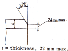
c) The end of the pipe is plain end unless otherwise specified. However, if the orderer specifies a bevel end, the shape shall be in accordance with the agreement between the delivery parties, and for pipes with a thickness of 22 mm or less, unless otherwise specified, figure 1 shall apply.
t: Thickness 22 mm or less
Figure 1-Shape of bevel end
5 Chemical constituents
The pipe is tested according to 10.1, and its molten steel analysis values are as per Table 3. If the orderer requires product analysis, the test is performed according to 10.1 and the values are as per Table 3. However, if necessary, alloy elements not specified in Table 3 may be added.
Table 3-Chemical composition
| Letter symbol of grade | Chemical Composition % | ||||||
| C | Si | Mn | P | S | Cr | Mo | |
| STPA 12 | 0.10~0.20 | 0.10~0.50 | 0.30~0.80 | 0.035 max. | 0.035 max. | −a)0.45 | 0.45~0.65 |
| STPA 20 | 0.10~0.20 | 0.10~0.50 | 0.30~0.60 | 0.035 max. | 0.035 max. | 0.50~0.80 | 0.45~0.65 |
| STPA 22 | 0.15max. | 0.50 max. | 0.30~0.60 | 0.035 max. | 0.035 max. | 0.80~1.25 | 0.45~0.65 |
| STPA 23 | 0.15max. | 0.50~1.00 | 0.30~0.60 | 0.030 max. | 0.030 max. | 1.00~1.50 | 0.45~0.65 |
| STPA 24 | 0.15max. | 0.50 max. | 0.30~0.60 | 0.030 max. | 0.030 max. | 1.90~2.60 | 0.87~1.13 |
| STPA 25 | 0.15max. | 0.50 max. | 0.30~0.60 | 0.030 max. | 0.030 max. | 4.00~6.00 | 0.45~0.65 |
| STPA 26 | 0.15max. | 0.25~1.00 | 0.30~0.60 | 0.030 max. | 0.030 max. | 8.00~10.00 | 0.90~1.10 |
Note a) If necessary, if Cr is added, it should not be added so that the type satisfies the specified values of other types and it becomes impossible to distinguish the types.
6 Mechanical properties
6.1 Tensile strength, yield point or yield strength, and elongation.
The pipe is tested according to 10.2.3, and its tensile strength, yield point or resistance, and elongation are as per Table 4. However, the minimum value of elongation when conducting tensile tests using No. 12 specimens or No. 5 specimens for pipes less than 8 mm in thickness, from the values in Table 4 for each 1 mm reduction in thickness The value obtained by subtracting 1.5 is rounded to an integer according to rule A of JIS Z 8401.
Table 4-Tensile strength, yield point or yield strength, and elongation
| Grade | Mechanical properties | |||||
| Tensile strength | Yield point or proofstress | Elongation % | ||||
| kgf/mm2 {N/mm2} | kgf/mm2 {N/mm2} | No. 11 or No.12 test piece | No. 5 test piece | No.4 test piece | ||
| Longitudinal | Transverse | Longitudinal | Transverse | |||
| STPA 12 | 39{382}min. | 21{206} min. | 30 min. | 25 min. | 24 min. | 19 min. |
| STPA 20 | 42{412}min. | 21{206} min. | 30 min. | 25 min. | 24 min. | 19 min. |
| STPA 22 | 42{412}min. | 21{206} min. | 30 min. | 25 min. | 24 min. | 19 min. |
| STPA 23 | 42{412}min. | 21{206} min. | 30 min. | 25 min. | 24 min. | 19 min. |
| STPA 24 | 42{412}min. | 21{206} min. | 30 min. | 25 min. | 24 min. | 19 min. |
| STPA 25 | 42{412}min. | 21{206} min. | 30 min. | 25 min. | 24 min. | 19 min. |
| STPA 26 | 42{412}min. | 21{206} min. | 30 min. | 25 min. | 24 min. | 19 min. |
Note 1N / mm2 = 1 MPa
Note) For pipes with an outer diameter of less than 40 mm, the elongation values in this table do not apply. However, it must be recorded.
When tensile test is carried out on No. 12 or No. 5 test piece for the pipe under 8mm in wall thickness, the minimum value of elongation shall be calculated by subtracting 1.5% from the values of elongation given in Table 4 for each 1mm decrease in wall thickness, and rounding off to an integer in accordance with JIS Z 8401. Examples of calculation are given in Reference Table 5.
Table 5-Minimum elongation values for No. 12 specimens (in the axial direction) and No. 5 specimens (in the direction perpendicular to the tube axis) of pipes less than 8 mm thick
| Grade | Shape of test piece | Elongation value relating to wall thickness % | ||||||
| Over 7mm, up to 8mm |
Over 6mm, up to and incl. 7mm |
Over 5mm, up to and incl. 6mm | Over 4mm, up to and incl. 5mm | Over 3mm, up to and incl. 4mm | Over 2mm up to and incl. 3mm | Over 1mm, up to and incl. 2mm | ||
| All grade | No.12 test piece | 30 | 28 | 27 | 26 | 24 | 22 | 21 |
| No.5 test piece | 25 | 24 | 22 | 20 | 19 | 18 | 16 | |
6.2 Flattening Resistance
The pipe shall be tested in accordance with 9.3 and the pipe shall be free from flaws or cracks on its wall surfaces. The distance between the flattening plates in this test shall be in accordance with the following formula.
Where H: distance between flattening plates(mm)
t: wall thickness of pipe(mm)
D: outside diameter of pipe(mm)
e: constant, 0.08
7.Hydrostatic Characteristic or Nondestructive Characteristic
The pipe is tested according to 10.3 and its hydraulic test characteristics or nondestructive test characteristics are as follows. Which property is used depends on the orderer's designation. If not specified, it shall be the manufacturer's choice.a) Water pressure test characteristics The water pressure test characteristics shall be as follows.
1) If the orderer specifies the test pressure, the pipe shall be the pressure for the water pressure test lower limit pressure, withstand this, and there shall be no leaks. If the test pressure specified by the orderer exceeds P or 20 MPa as calculated by equation (1), the test pressure is in accordance with the agreement between the delivery parties.
Water pressure test lower limit pressure shall be in increments of 0.5 MPa for less than 10 MPa and in increments of 1 MPa for 10 MPa or more. In the case of calculation according to equation (1), round in increments of 0.5 MPa or 1 MPa as well.
where,
P: Test pressure (MPa)
t: Tube thickness (mm)
D: Outer diameter of tube (mm)
s: 60% (N / mm2) of the specified minimum value of yield point or load resistance in Table 4
2) If the orderer does not specify the test pressure, the tube will withstand this when the hydraulic test lower limit pressure shown in Table 6 is applied, and there shall be no leaks.
In the case of pipes other than those listed in Table 7, calculate the water pressure test lower limit pressure as follows.
2.1) In the case of the outer diameter range in Table 7, select the smaller outer diameter between the outer diameters corresponding to this table.
2.2) If the thickness is within the range of the schedule number of the thickness of the outer diameter selected in 2.1), select the larger thickness among the thicknesses corresponding to this table.
2.3) According to the outer diameter and thickness schedule numbers selected in 2.1) and 2.2), the test is carried out at a pressure higher than the lower limit pressure of the water pressure test in Table 6.
2.4) Water pressure test for pipes other than the dimensions in Table 7 which do not satisfy the conditions of 2.1) and 2.2) The lower limit pressure of the pipe shall be in accordance with the agreement between the delivering parties.
2.5) If the water pressure test lower limit pressure of the schedule No. selected in 2.1) and 2.2) exceeds the test pressure P calculated by equation (1), P instead of the water pressure test lower limit pressure selected in Table 6 Water pressure test Perform the test as the lower limit pressure.
Table 6-Water pressure test lower limit pressure ,Unit MPa
| Sch | 10 | 20 | 30 | 40 | 60 | 80 | 100 | 120 | 140 | 160 |
| Water pressure test lower limit pressure | 2.0 | 3.5 | 5.0 | 6.0 | 9.0 | 12 | 15 | 18 | 20 | 20 |
b) Nondestructive testing characteristics The tube is subjected to nondestructive testing either ultrasonic testing or eddy current testing, and the nondestructive testing characteristics are as follows. However, it may be replaced with ultrasonic flaw test or eddy current flaw test by agreement between delivery parties, and may be by other nondestructive test specified in Japanese Industrial Standards. The acceptance criteria in this case shall be equal to or greater than those of the ultrasonic flaw test or the eddy current flaw test.
1) Contrast sensitivity classification according to JIS G 0582 or a sensitivity classification stricter than this There shall be no signal that is equal to or greater than the signal from an artificial flaw of the test specimen.
2) Comparison of artificial flaws for flaw detection sensitivity setting according to JIS G 0583 EY or a sensitivity category more severe than that There shall be no signal equal to or greater than the signal from the artificial flaws of the test piece.
8.Dimensions, Mass and Dimensional Tolerances
8.1Dimensions and Mass
The outside diameter, wall thickness and mass of the pipe shall be as specified in Attached Table 7.
8.2 Dimensional Tolerances
The tolerances on outside diameter, wall thickness and deviation in wall thickness of the pipe shall be as specified in Table 8. Further, in the case where the pipe length is specified, the tolerances shall be on the plus side.
Table 8 Tolerances on Outside Diameter, Wall Thickness and Deviation in Wall Thickness
| Division | Tolerances on outside diameter | Tolerances on wall thickness | Tolerance on deviation in wall thickness | |||
| Up to 50mm 【 0.5mm | ||||||
| Hot | 50mm and over, up to 160mm 【 1% | |||||
|
finished seamless |
160mm and over, up to 200mm 【 1.6mm |
≤Up to 4mm 【 0.5mm ≤4mm and over 【 12.5% |
Up to and incl. 20% of wall thickness |
|||
| 200mm and over 【 0.8 % | ||||||
| steel pipe | However, for pipes 350mm and over in diameter, the length of circumference may substitute as | |||||
| a basis for the tolerances. In this case, the tolerances shall be 【 0.5%. | ||||||
| Cold | Up to 40mm 【 0.4mm | |||||
|
finished seamless |
40mm and over 【 0.8% However, for pipes 350mm and over in diameter, the length of circumference may substitute as |
≤Up to 2mm 【 0.2mm ≤2mm and over 【10% |
- |
|||
| steel pipe | a basis for tolerances. Inthis case, the tolerances shall be 【 0.5% | |||||
Remarks
(1)The deviation in wall thickness means the ratio of the difference between the maximum and the minimum of the measured thickness of a wall in the same section to the specified wall thickness. This shall not be applied to pipes under 5.6mm in wall thickness.
(2)When the length of circumference is used as f basis for the tolerances, either the measured value of the length of circumference itself or the outside diameter derived from the measured value may be used as the criteria. In both cases, the same value【 0.5 % shall be applied as the tolerances. The diameter (D) and the length of circumference (l) shall be calculated reversibly from the following formula.
l =ヰ · D Where ヰ =3.1416
(3)In the case where compliance with the tolerances on wall thickness in the above table is clearly confirmed in such a local portion as under repairs, the tolerances on the outside diameter in the above table shall not be applied.
9 Appearance
The appearance is as follows.
a) The pipe should be practically straight and at both ends perpendicular to the pipe axis.
b) The inner and outer surfaces of the pipe shall be well finished and have no detrimental disadvantages in use.
c) If surface treatment is to be carried out, it may be by grinder or machining, but the product thickness after maintenance should be within the thickness tolerance.
In addition, welding repair should not be conducted.
d) The marks of care must follow the shape of the tube smoothly.
10 Test
10.1 Analysis test
10.1.1 General items of analytical test and
How to take samples for analysis The general items of analysis tests and how to take samples for analysis are as described in Clause 8 (chemical components) of JIS G 0404. When the orderer requests product analysis, the method of sampling shall be as specified in Clause 4 of JIS G 0321 (sampling method for analysis).
10.1.2 Analysis method
The method of molten steel analysis is in accordance with JIS G 0320. The method of product analysis is in accordance with JIS G 0321.
10.2 Mechanical test
10.2.1 General items of mechanical testing
The general items of mechanical tests are in accordance with Clause 7 (general requirements) and Clause 9 (mechanical properties) of JIS G 0404. However, how to pick the test material to be used for mechanical test is Class A of JIS G 0404 7.6 (Test specimen collection conditions and test specimen).
10.2.2 How to pick the test material and the number of test pieces
How to pick the test materials for tensile test and flat test and the number of test pieces, sample the same size 1) and simultaneous heat treatment 2) 3) every 50 tubes and one sample from each fraction From each, take one tensile test piece and one flat test piece.
Note 1) The same dimension means the same outer diameter and the same thickness.
2) Simultaneous heat treatment when using a continuous furnace refers to continuous heat treatment under the same heat treatment conditions, and when the continuous furnace is stopped, it is not included in the simultaneous heat treatment.
3) When sample materials are sampled in the same molten steel unit, the same heat treatment conditions may be used instead of simultaneous heat treatment.
10.2.3 Tensile test
The tensile test pieces and tensile test methods shall be as follows.
a) Test specimen Take any of JIS Z 2241, No. 11, No. 12A, No. 12B, No. 12C, No. 4 or No. 5 test piece and collect it from the pipe. However, test specimen No. 4 shall be 14 mm in diameter (the distance between marks is 50 mm).
b) Test method According to JIS Z 2241.
10.2.4 Hemp exam
The flat test pieces and the flat test method shall be as follows.
The flat test may be omitted unless otherwise specified by the orderer 4).
Note 4) Tests may be omitted at the discretion of the manufacturer, but flatness means that the requirements must be satisfied.
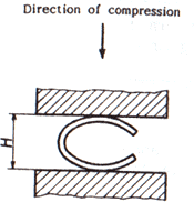
a) Test specimen Cut a length of at least 50 mm from the end of the tube and use it as a test specimen. However, in the case of a tube with a thickness of 15% or more of the outer diameter, it may be a C-shaped test piece from which part of the circumference of the annular test piece has been removed.
b) Test method: Insert the test piece between two flat plates at normal temperature, compress it until the distance between the flat plates becomes less than the value specified in 6.2, and make it flat. Examine. Place the C-shaped test piece as shown in Fig.2.
H: distance between plates
Fig. 2-Flat test (C-type test piece)
10.3 Water pressure test or nondestructive test
Whether the water pressure test or the nondestructive test is applied shall be the manufacturer's choice if not specified by the orderer.
a) Test frequency For each water pipe, either water pressure test or non-destructive test.
b) Test method
1) Water pressure test When pressure is applied to the pipe for more than 5 seconds by applying a pressure higher than the lower limit of the water pressure test specified in Clause 7 a), withstand this and check whether a leak has occurred.
2) Nondestructive test The test method shall be in accordance with JIS G 0582 or JIS G 0583. However, the test method for performing other nondestructive testing prescribed in other Japanese Industrial Standards is based on the agreement between the delivering and receiving parties.
11 inspection and re-inspection
11.1 Inspection
The inspection is as follows.
a) General items of inspection shall be in accordance with JIS G 0404.
b) Chemical constituents shall conform to Clause 5.
c) Mechanical properties shall conform to Clause 6.
d) Water pressure test characteristics or non-destructive test characteristics shall conform to clause 7.
e) Dimensions, mass and dimensional tolerances shall conform to clause 8.
f) The appearance shall conform to Clause 9.
g) When applying some or all of the items of the Special Quality Regulations specified in Annex JA according to the agreement between delivery parties, the applicable regulations shall be met.
11.2 Retest
Tubes that do not pass the mechanical test may be retested in accordance with JIS G 0404 9.8 (retest) to determine pass or fail.
12 views
The following items shall be indicated for each pipe that has passed the inspection. However, if there is a need for a tube with a small outer diameter and the orderer, it may be bundled and displayed in a suitable manner in bundles. The order of display is not specified. In addition, when approval of the orderer is obtained, part of the approval may be omitted.
a) type of symbol
b) a symbol representing a manufacturing method
The symbols representing the manufacturing method are as follows. However,-may be blank.
1) Hot finish seamless steel pipe -S-H
2) Cold finish seamless steel pipe -S-C
c) Dimensions. The dimensions are nominal diameter × nominal thickness, or outer diameter × thickness.
Example 50A × Sch40 or 60.5 × 3.9
d) Manufacturer name or its code
e) Symbol indicating the designation of special quality regulations: Z (when designated)
13 Report
The manufacturer shall submit the inspection documents to the orderer unless otherwise specified. The report is in accordance with Clause 13 (Report) of JIS G 0404. The type of inspection document shall be symbol 2.3 (delivery test report) or 3.1.B (inspection certificate 3.1.B) of JIS G 0415 Table 1 (generalization table of inspection document) unless otherwise specified at the time of ordering. .
When alloying elements not specified in Table 3 are intentionally added, the contents of added alloying elements are added to the score sheet.