JIS G3456 Carbon Steel Pipes for High Temperature Service
JIS G3456 Carbon Steel Pipes for High Temperature Service
1. Scope
This Japanese Industrial Standard specifies the carbon steel pipes, hereinafter referred to as the "pipes", mainly used for piping at a temperature over 350℃.
Remarks
1. When previously agreed upon by the manufacturer, the purchaser may designate one or all of the supplementary quality requirements Z 2, Z 3 and Z 4 specified in Appendix, in addition to the items specified in this text.
Appendix Z2 Elevated Temperature Yield Point or Proof Stress
Appendix Z3 Ultrasonic Examination
Appendix Z4 Eddy Current Examinaion
2. The units and numerical values given in { } in this Standard are based on the International System of Units (SI) and are appended for informative reference.
Further, the traditional units accompanied by numerical values in this Standard shall be converted to the SI units and numerical values on Jan. 1, 1991.
2. Grade and Symbol
Steel Grade: STPT 370 ,STPT 410 ,STPT 480
Steel Grade: STPT 370 ,STPT 410 ,STPT 480
The pipe shall be classified into three grades and their letter symbols shall be as given in Table 1.
Table 1 Steel Grade of JIS G3456 Carbon Steel Pipes
4. Chemical Composition
The pipe shall be tested in accordance with 9.1 and the resulting ladle analysis values shall conform to Table 3.
Reference Table Calculated Examples of Elongation Applied to No. 12(Longitudinal) and No. 5 (Transverse) Test pieces for Pipes under 8mm in Wall Thickness
Table 1 Steel Grade of JIS G3456 Carbon Steel Pipes
| Letter symbol of grade | (Informative reference) Traditional symbol |
| STPT 370 | STPT 38 |
| STPT 410 | STPT 42 |
| STPT 480 | STPT 49 |
3. Method of Manufacture
3.1 The pipe shall be manufactured from coarse-grained killed steel by the seamless or electric resistance welding process. However, the pipe of grade STPT 480 shall be manufactured by the seamless process.
3.2 The pipe shall be subjected to the heat treatment specified in Table 2. the heat treatment other than specified in Table 2 shall be agreed upon by the purchaser and the
manufacturer
Table 2 Heat treatment
| Grade | Hot finished seamless steel pipe | Cold finished seamless steel pipe | Hot finished electric resistance welded steel pipe |
Electric resistance welded steel pipe other than hot finished
|
| STPT370 |
As manufactured. However, low temperature annealing or normalizing may be applied, as necessary.
|
Low temperature annealed or normalized.
|
As manufactured. However, low temperature annealing
or normalizing may be applied, as necessary.
|
Low temperature annealed or
normalized.
|
| STPT410 | ||||
| STPT480 | - | - |
3.3 When required by the purchaser, the pipe may be furnished with the bevel end(1).
Note (1) Unless otherwise specified, the shape of the bevel end shall be as shown in Fig. 1.

4. Chemical Composition
The pipe shall be tested in accordance with 9.1 and the resulting ladle analysis values shall conform to Table 3.
Table 3 Chemical Composition Of JIS G3456 Carbon Steel Pipes
| Grade | Chemical Composition % | ||||
| C | Si | Mn | p | S | |
| STPT 370 | 0.25 max. | 0.10~0.35 | 0.30~0.90 | 0.035 max. | 0.035 max. |
| STPT 410 | 0.30 max. | 0.10~0.35 | 0.30~1.00 | 0.035 max. | 0.035 max. |
| STPT 480 | 0.33 max. | 0.10~0.35 | 0.30~1.00 | 0.035 max. | 0.035 max. |
Remarks
When the product analysis is required by the purchaser, the tolerances for the above-mentioned values shall conform to Table 2 and Table 1 specified in JIS G 0321 for seamless steel pipes and electric resistance welded steel pipes, respectively.
5. Mechanical Properties
5.1 Tensile Strength, Yield Point or Proof Stress and Elongation
The pipe shall be tested in accordance with 9.2 and the resulting tensile strength, yield point or proof stress and elongation of the pipe shall comply with Table 4.
Table 4 Mechanical Properties of JIS G3456 Carbon Steel Pipes
| Letter symbol of grade | Mechanical Properties | |||||
| Tensile strength | Yield strength | Elongation % | ||||
| kgf/m㎡ {N/ m㎡} | kgf/m㎡ {N/ m㎡} | No.11 and No.12 test pieces | No. 5 test pieces | No. 4 test piece | ||
| Longitudinal | Transverse | Longitudinal | Transverse | |||
| STPT370 | 38 {373}min | 22{216} min | 30 min | 25 min | 23 min | 28 min |
| STPT 410 | 42{412}min | 25{245} min | 25 min | 20 min | 19 min | 24 min |
| STPT 480 | 49{481} min. | 28{275} min. | 25 min. | 20 min. | 17 min. | 22 min. |
Remarks
1. When the tensile test for pipes under 8mm in wall thickness is carried out with No. 12 or No. 5 test piece, the minimum value of elongation shall be obtained by subtracting 1.5 % from the values of elongation given in Table 4 for each 1mm decrease in wall thickness, and rounding off the value to an integer in compliance with JIS Z 8401. Examples of calculation are given in Reference Table.
2. The value of elongation given in Table 4 shall not be applied to the pipe whose outside diameter is under 40mm. However, the value of elongation shall be recorded.
3. When a tensile test piece is taken from the electric resistance welded steel pipe, No. 12 or No. 5 test piece shall be taken from the portion which does not involve welded seam
Reference Table Calculated Examples of Elongation Applied to No. 12(Longitudinal) and No. 5 (Transverse) Test pieces for Pipes under 8mm in Wall Thickness
| Letter symbol of grade | shape of test piece | Elongation value relating to wall thickness % | ||||||
|
Over 7mm
to and excl.8mm
|
Over 6mm
to and excl7mm
|
Over 5mm
to and excl.6mm
|
Over 4mm
to and excl. 5mm
|
Over 3mm
to and excl. 4mm
|
Over 2mm
to and excl. 3mm
|
Over 1mm
to and excl. 2mm
|
||
| STS 370 | No12 test piece | 30 | 28 | 27 | 26 | 24 | 22 | 21 |
| No5. test piece | 25 | 24 | 22 | 20 | 19 | 18 | 16 | |
|
STS 410 STS 480 |
No12 test piece | 25 | 24 | 22 | 20 | 19 | 18 | 16 |
| No5. test piece | 20 | 18 | 17 | 16 | 14 | 12 | 11 | |
5.2 Flattening Resistance The pipe shall be tested in accordance with 9.3 and the pipe shall be free from flaws or cracks on its wall surface.
In this case, the distance between the flattening plates shall be calculated from the following formula.

Where
Where
H : distance between flattening plates (mm)
t: wall thickness of pipe (mm)
D: outside diameter of pipe (mm)
e: constant which varies depending on the grade of pipe
0.08 for STPT 370
0.07 for STPT 410 and STPT 480
5.3 Bending Resistance For the pipe whose outside diameter is 50mm or under, the purchaser may specify the bending test in lieu of the flattening test. The pipe shall be tested in Accordance with 9.4 and its wall surfaces shall be free from the occurrence of flaws or cracks. In this test the pipe is bent through 90x around an inside radius that is 6 times its outside diameter.
However, the purchaser may specify the bend test of which the bent angle is 180x and bending inside radius is 4 times the outside diameter.
Attached Table 1.
6. Test
The pipe shall be tested in accordance with 9.5 and the resulting hydrostatic characteristic or nondestructive characteristic shall conform to either of the following two. The preference shall be in accordance with the designation made by the purchaser or left to the discretion of the manufacturer.
6.1 When the hydrostatic pressure specified by the purchaser or, unless otherwise specified, the values given in Attached Table 1 is applied, the pipe shall withstand it without leakage. Inthis case, the purchaser may specify values of pressure lower or higher than those given in Attached Table 1.
When a hydrostatic pressure test is made in compliance with the designation of the purchaser and the test pressure exceeds either 200 kgf/㎠ {196 bar} or the value P calculated from the following formula, the test pressure shall be agreed upon by the purchaser and the manufacturer. The designated hydrostatic test pressure shall be graduated in 5kgf/㎠ {4.9 bar}.
Attached Table 1.
P= 200st / D
Where
P: test pressure[ kgf/㎠{10 -1 bar( 2 )}
t: wall thickness(mm)
D: outside diameter of pipe(mm)
s: 60 % of the minimum value of yield point or proof stress specified in Table 4 [kgf/mm 2 {N/mm 2 }]
Note ( 2 ) 1bar = 10 5 Pa
6.2 Either an ultrasonic examination or an eddy current examination shall be made on the pipe, and there shall be no signal greater than those produced by the artificial defects of the reference test block which is the division UD of the working sensitivity specified in JIS G 0582 or the division EY of the working sensitivity specified in JIS G 0583, respectively.
7. Appearance
7.1 The pipe shall be practically straight, and its both ends shall be at right angles to the axes.
7.2 The inside and outside surfaces of the pipe shall be well-finished, and free from defects detrimental to practical use.
8. Dimensions, Mass and Dimensional Tolerances
8.1 Dimensions and Mass
The outside diameter, wall thickness and mass of the pipe shall be as specified in Attached Table 2.
8.2 Dimensional Tolerances The tolerances on outside diameter, wall thickness and deviation in wall thickness of the pipe shall be as specified Table 5.
In the case where the pipe length is specified by the purchaser, the tolerances on the pipe length shall be on the plus side.
| Division | Tolerances on outside diameter |
Tolerances on wall thickness
|
Tolerance on deviation in wall thickness
|
|
Hot finished seamless steel
pipe
|
Up to 50 mm 【0.5mm |
≤Up to 4 mm
【0.5mm
|
Up to and incl. 20 % of
wall thickness
|
|
50mm and over, up to 160mm
【1%
|
|||
|
160mm and over, up to 200mm
【1.6mm
|
≤4mm and over
【12.5%
|
||
| 200mm and over 【0.8% | |||
|
However, for pipes 350mm and over in diameter, the length of circumference may
substitute as a basis for tolerances, In this case, the tolerances shall be 【0.5%.
|
|||
|
Cold finished seamless steel
pipe and electric resistance
welded steel pipe
|
Up to 40mm 【0.3mm |
≤Up to 2 mm
【0.2mm
|
- |
| 40mm and over 【0.8% |
≤2mm and over
【10%
|
||
|
However, for pipes 350mm and over in diameter, the length of circumference may
substitute as a basis for tolerances. In this case, the tolerances shall be 【0.5%
|
Remarks
1. The deviation in wall thickness means the ratio of the difference between the maximum and the minimum of the measured thickness of a wall in the same section to the specified wall thickness. This shall not be applied to pipes under 5.6mm in wall thickness.
2. When the length of circumference is used as a basis for the tolerances, either the measured value of the length of circumference itself or the outside diameter derived from the measured value may be used as the criteria. In both cases, the same value 【 0.5 % shall be applied as the tolerances. The outside diameter (D) and the length of circumference (l) shall be calculated reversibly from the following formula.
ラ=ヰ · D where ヰ=3.1416
8.3 In the case where compliance with the tolerances on wall thickness in the above table is clearly confirmed in such a local portion as under repaired, the tolerances on the outside diameter in the above table shall not be applied.
9. Tests
9.1 Chemical Analysis
9.1.1 Chemical Analysis
General matters about chemical analysis and method of sampling specimens for analysis shall be in accordance with 3. in JIS G 0303.
9.1.2 Analytical Method The analytical method shall be in accordance with one of the following Standards.
JIS G 1253
JIS G 1256
JIS G 1257
JIS G 1214
JIS G 1215
JIS G 1211
JIS G 1212
JIS G 1213
9.2 Tensile Test
9.2.1 Test piece
The test specimen shall be No. 11, No. 12 A, No. 12 B, No.12 C, No. 4 or No. 5 test piece specified in JIS Z 2201 and shall be cut off from the end of the pipe. In this case, the gauge length for No. 4 test piece shall be 50mm.
9.2.2 Test Method
The test method shall be in accordance with JIS Z 2241.
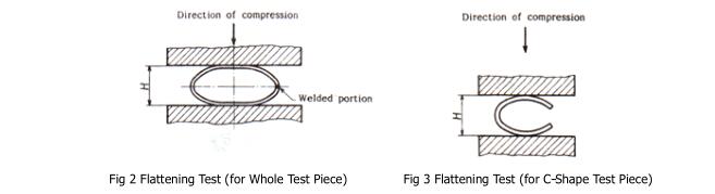
9.3 Flattening Test
9.3.1 Test Piece
A test piece 50mm or over in length shall be cut off from the end of a pipe. For the pipe whose wall thickness is 15 % or over of the outside diameter, a C-shape test piece made by removing part of the circumference of a whole test piece may be used.
9.3.2 Test Method
The test piece shall be placed between two flat plates at ordinary temperature and flattened by compression until the distance between the plates comes to the specified value, and checked for the occurrence of flaws or cracks on its wall surface. An electric resistance welded steel pipe shall be placed with the welded portion at right angles to the direction of compression as shown in Fig. 2, and a C-shape test piece shall be placed as shown in Fig. 3.
9.4 Bending Test
9.4.1 Test Piece
An appropriate length shall be cut off from the end of a pipe to be made into a test piece.
9.4.2 Test Method
The test piece shall be bent through the angle around a cylinder with an inside radius specified in 4.3 at ordinary temperature, and checked for the occurrence of flaws or cracks on its wall surface. In the case of an electric resistance welded steel pipe, the welded portion shall be placed in the outermost part of the bent portion.
9.5 Hydrostatic Test or Nondestructive Examination Either the hydrostatic test or the nondestructive examination shall be made in accordance with 9.5.1 or 9.5.2, respectively.
9.5.1 When the pipe is subjected to hydrostatic pressure and kept under the specified pressure, it shall withstand the pressure without leakage.
9.5.2 The test method of nondestructive examination shall be in accordance with either JIS G 0582 or JIS G 0583.
10. Inspection
10.1 General matters of inspection shall be as specified in JIS G 0303.
10.2 The chemical composition, mechanical properties, hydrostatic or nondestructive characteristic, dimensions and appearance shall conform to 3., 4., 5., 6. and 7. However, the nondestructive examination may be replaced by appropriate nondestructive examination other than those specified in 9.5 (2) when agreed upon by the purchaser and the manufacturer.
Further, when the supplementary quality requirements given in Appendix are specified by agreement by the purchaser and the manufacturer, the results of inspection shall conform to the relevant requirements specified in Z 2, Z 3, or Z 4.
10.3 Either the hydrostatic test or the nondestructive examination shall be performed for each pipe.
10.4 The number of specimens for the product analysis shall be agreed upon by the purchaser and the manufacturer.
10.5 The method of sampling test specimens and the number of test pieces for tensile test and flattening test or bending test shall be as follows. From the pipe as manufactured, take one pipe as the specimen from each 50 pipes or its fraction of the same dimensions ( 3 ), for the pipe to be heat-treated, take one pipe as the specimen from each 50 pipe or its fraction of the same dimensions ( 3 ) and of the concurrent heat treatment, and in any case from the test specimen take one tensile test piece. Further, from the pipe 50mm or under in outside diameter, take one test piece for flattening test or bending test, and from the pipe over 50mm in outside diameter, take one flattening test piece.
Note ( 3 ) The "same dimensions" here means the same wall thickness concurrent with the same outside diameter.
11.Reinspection
The pipe may be retested in accordance with 4.4 in JIS G 0303 for final acceptance.
12. Marking
Each pipe having passed the inspection shall be marked with the following items. However, in the case of smaller pipes or on a request from the purchaser, pipes may be bundled together and marked for each bundle by suitable means. In either case, the order of arranging the items is not specified.
When approved by the purchaser, part of the items may be omitted.
(1) Letter symbol of grade
(2) Letter symbol indicating the manufacturing process ( 4 )
(3) Dimensions ( 5 )
(4) Manufacturer's name or its abbreviation
(5) Letter symbol indicating the supplementary quality requirement, Z
note ( 4 )
The letter symbol indicating the manufacturing process shall be as follows, provided that the dash may be replaced by a blank.
Hot-finished seamless steel pipe -S-H
Cold finished seamless steel pipe -S-C
Electric resistance welded steel pipe neither hot finished nor cold finished -E-G
Hot finished electric resistance welded steel pipe -E-H
Cold finished electric resistance welded steel pipe -E-C
Note ( 5 )
The dimensions shall be expressed as follows
Nominal diameter X nominal wall thickness or outside diameter X wall thickness
Example: 50A × Sch80
13. Report
The manufacturer shall, as a rule, submit to the purchaser the report on the test results, method of manufacture, ordered dimensions, quantity and work lot number traceable to
the manufacturing conditions, etc.