JIS G3452 Carbon steel pipes for ordinary piping
JIS G3452
Carbon steel pipes for ordinary piping
1 Scope
This Japanese Industrial Standard specifies the carbon steel pipes (hereafter referred to as "pipes") used for piping to convey steam, water (except public water supply service),oil, gas, air, etc. at comparatively low working pressures. This Standard is applicable to pipes with an outside diameter of 10.5 mm to 508.0 mm.
2 Normative references
The following standards contain provisions which, through reference in this text,constitute provisions of this Standard. The most recent editions of the standards (including amendments) indicated below shall be applied.
JIS B 0203 Taper pipe threads
JIS B 0253 Gauges for taper pipe threads
JIS B 2301 Screwed type malleable cast iron pipe fittings
JIS B 2302 Screwed type steel pipe fittings
JIS G 0320 Standard test method for heat analysis of steel products
JIS G 0404 Steel and steel products-General technical delivery requirements
JIS G 0415 Steel and steel products-Inspection documents
JIS G 0582 Automated ultrasonic examination of steel pipes and tubes
JIS G 0583 Automated eddy current examination of steel pipes and tubes
JIS H 0401 Test methods for hot dip galvanized coatings
JIS H 2107 Zinc ingots
JIS H 8641 Hot dip galvanized coatings
JIS Z 2241 Metallic materials-Tensile testing-Method of test at room temperature
JIS Z 8401 Guide to the rounding of numbers
3 Classification and symbols
Pipes shall be classified into one grade and the designation of grade, designation of manufacturing method and classification of zinc-coating shall be as given in table 1.
4 Manufacturing method
The manufacturing method shall be as follows.
a) Pipes shall be manufactured by electric resistance welding or butt welding.
b) Pipes shall be delivered as manufactured. However, the cold-finished pipes shall be annealed after manufacturing.
c) Both ends of pipes of nominal diameter 300A or under in table 5 shall be threaded or plain-ended, and those of nominal diameter 350A or over shall be plain-ended.
When specified by the purchaser, pipes may be furnished with bevel ends. The shape thereof shall be upon the agreement between the purchaser and the manufacturer
d) For threaded pipes, taper threads specified in JIS B 0203 shall be applied on both ends, and a socket as in JIS B 2301 or JIS B 2302 shall be screwed into one end of the threads. The other end with a socket not screwed shall be provided with a thread protecting ring or protected by other suitable means. When specified by the purchaser, the threaded pipe may dispense with a socket. The taper threads shall be inspected in accordance with JIS B 0253.
e) For white pipes, the pipes and sockets shall be zinc-coated before threading. In this case, black pipes and sockets that passed the inspection shall be thoroughly cleaned by sand blasting, pickling, etc., then be zinc-coated by hot dip galvanized coating.
f) Zinc used for zinc-coating shall be the distilled zinc ingot Class 1 specified in JIS H 2107 or zinc ingot at least equivalent thereto.
g) Other general matters of zinc-coating shall be in accordance with JIS H 8641.
5 Chemical composition
Pipes shall be tested in accordance with 11.1, and the heat analysis values shall be as given in table 2. As necessary, alloy elements not specified in table 2 may be added.
b) The pipe length shall be 3 600 mm or over. Tolerances on the length shall be zero for the minus side, and not be specified for the plus side.
10 Appearance
The appearance of pi pes shall be as follows.
a) Pipes shall be practically straight, with the both ends practically perpendicular to the pipe axis.
b) The inside and outside surfaces of pipes shall be well-finished and free from defects that are detrimental to practical use. Especially, the inside and outside surfaces of white pipes shall be practically smooth.
c) Black pipes may be repaired by grinding or machining, provided that the thickness after repairing shall be within the given tolerances of wall thickness.
d) The surface of all repaired parts shall blend smoothly into the contour of the pipe.
e) Upon the agreement between the purchaser and the manufacturer, pipes may be coated (e.g. zinc rich painting, epoxy coating, primer coating, etc.) on the outside or inside surface, or on the both surfaces.
11 Tests
11.1 Chemical analysis
11.1.1 General matters of chemical analysis and sampling method General matters of chemical analysis and sampling method shall be in accordance with clause 8 of JIS G 0404.
11.1.2 Analytical method
The heat analysis shall be in accordance with JIS G 0320.
11.2 Mechanical test
11.2.1 General
General matters of mechanical test shall be in accordance with clauses 7 and 9 of JIS G 0404. The sampling method for mechanical tests in 7.6 of JIS G 0404 shall be in accordance with Class A.
11.2.2 Sampling method and number of test pieces
The sampling method and the number of test pieces for mechanical test shall be as given in table 5. From each sample, a tensile test piece, and a flattening test piece or a bend test piece shall be sampled. In the case of white pipes, the sample shall be taken from pipes before zinc-coating.
11.2.3 Tensile test
The tensile test piece and the tensile test method shall be as follows.
a) Test piece The test piece shall be one of No. 11, No. 12 (No. 12A, No. 12B and No. 12C) or No.5 specified in JIS Z 2241. For No. 11 and No. 12 test pieces, the sampling direction shall be parallel to the pipe axis. For No.5 test pieces, the sampling direction shall be perpendicular to the pipe axis. No. 12 or No.5 test pieces shall be taken from the seamless parts.
b) Test method The test method shall be in accordance with JIS Z 2241.
11.2.4 Flattening test
The flattening test piece and the test method shall be as follows.
a) Test piece The length of test piece shall be 50 mm or more.
b) Test method The test piece shall be placed between two flat plates at ordinary temperature and flattened by compression until the distance H between the plates becomes equal to or below the specified value in 6.2, and shall be checked for cracks on its wall surface. In this test, the pipe shall be placed with the weld at such position that the line connecting the pipe centre and the weld is perpendicular to the direction of compression, as given in figure 1.
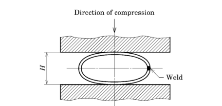
Figure 1 Flattening test
11.2.5 Bend test
The bend test piece and the test method shall be as follows.
a) Test piece The test piece shall have a length suitable for the test.
b) Test method The test piece shall be bent around a cylinder at ordinary temperature through a bending angle not less than that specified in 6.3, and with the inside bending radius not more than that specified in 6.3, and it shall be checked for cracks on the wall surface. In this case, the pipe shall be placed with the weld positioned at approximately 90° from the outermost part of the bent portion.
11.3 Zinc-coating test
The zinc-coating test shall be as follows.
a) Sampling method and number of test pieces For copper sulphate test pieces,one sample product shall be taken from each group of 500 pipes or its fraction of the same dimensions, and one test piece shall be taken from each end of the sample product.
b) Test piece The test piece shall be a tubular test piece approximately 60 mm in length. When the outside diameter is large, the test piece may be cut to a length suitable for the measurement.
c) Test method The copper sulphate test for zinc-coating shall be carried out in accordance with clause 6 of JIS H 0401. It shall be checked whether the result reaches the end point when the pipe is dipped in the copper sulphate solution five times (duration of each dipping: 1 min).
11.4 Hydrostatic test or nondestructive test
The hydrostatic test or nondestructive test shall be as follows.
a) Frequency of test The hydrostatic test or nondestructive test shall be carried out for each one of pipes.
b) Test method
1) Hydrostatic test The pipe shall be held under the minimum hydrostatic test pressure specified in 8 a) for at least 5 s, and then examined if it endures the pressure without leakage.
2) Nondestructive test The test method shall be as follows.
2.1) The ultrasonic testing shall be in accordance with JIS G 0582. The test may be conducted by the category stricter than division DE.
2.2) The eddy current testing shall be in accordance with JIS G 0583. The test may be conducted by the category stricter than division EZ.
12 Inspection and re-inspection
12.1 Inspection
The inspection shall be as follows.
a) General matters of inspection shall be in accordance with JIS G 0404.
b) The chemical composition shall conform to clause 5.
c) The mechanical properties shall conform to clause 6.
d) The uniformity of zinc-coating shall conform to clause 7.
e) The hydrostatic test characteristics or nondestructive test characteristics shall conform to clause 8.
f) The dimensions shall conform to clause 9.
g) The appearance shall conform to clause 10.
12.2 Re-inspection
Pipes which failed in mechanical test or the zinc-coating test may be further evaluated for acceptance by conducting a retest specified in 9.8 of JIS G 0404.
13 Marking
Each pipe which passed the inspection shall be marked with the following items.However, the smaller pipes in outside diameter or other pipes specified by the purchaser may be bundled together and marked for each bundle by a suitable means. The arrangement of items is not specified. When approved by the purchaser, part of the items may be omitted to such extent that the product can be identified.
a) Designation of grade
b) Designation of manufacturing process
Designations of manufacturing process shall be as follows. The dash may be omitted.
Electric resistance welded steel pipes - E - G
Hot-finished electric resistance welded steel pipes - E - H
Cold-finished electric resistance welded steel pipes - E - C
Butt-welded steel pipes - B
c) Dimensions Dimensions shall be marked by "nominal diameter".
d) Manufacturer's name or its identifying brand
14 Test report
The manufacturer shall submit an inspection document to the purchaser when previously required. The inspection document shall conform to clause 13 of JIS G 0404.
The type of the inspection document shall be the standard designation 3.1 in table 1 of JIS G 0415, unless otherwise specified at the time of ordering.
In addition, if any alloy elements other than those given in table 2 are intentionally added, the content of the added alloy elements shall be appended to the inspection document.
Carbon steel pipes for ordinary piping
1 Scope
This Japanese Industrial Standard specifies the carbon steel pipes (hereafter referred to as "pipes") used for piping to convey steam, water (except public water supply service),oil, gas, air, etc. at comparatively low working pressures. This Standard is applicable to pipes with an outside diameter of 10.5 mm to 508.0 mm.
2 Normative references
The following standards contain provisions which, through reference in this text,constitute provisions of this Standard. The most recent editions of the standards (including amendments) indicated below shall be applied.
JIS B 0203 Taper pipe threads
JIS B 0253 Gauges for taper pipe threads
JIS B 2301 Screwed type malleable cast iron pipe fittings
JIS B 2302 Screwed type steel pipe fittings
JIS G 0320 Standard test method for heat analysis of steel products
JIS G 0404 Steel and steel products-General technical delivery requirements
JIS G 0415 Steel and steel products-Inspection documents
JIS G 0582 Automated ultrasonic examination of steel pipes and tubes
JIS G 0583 Automated eddy current examination of steel pipes and tubes
JIS H 0401 Test methods for hot dip galvanized coatings
JIS H 2107 Zinc ingots
JIS H 8641 Hot dip galvanized coatings
JIS Z 2241 Metallic materials-Tensile testing-Method of test at room temperature
JIS Z 8401 Guide to the rounding of numbers
3 Classification and symbols
Pipes shall be classified into one grade and the designation of grade, designation of manufacturing method and classification of zinc-coating shall be as given in table 1.
Table 1 Designation of grade, designation of manufacturing method and classification of zinc-coating
| Designation of grade | Designation of manufacturing method | Classification of zinccoating | ||
| Manufacturing method | Finishing method | Marking | ||
| SGP |
Electric resistance welded: E Butt welded: B |
Hot-finished: H Cold-finished: C As electric resistance welded: G |
Designation of man ufacturing method shall bein accordance with 13b). |
Black pi pes: not zinccoated pipes White pipes: zinc-coated pipes |
|
When it is necessary to identify the white pipes by a designation in the drawing, document, etc., -ZN shall be suffixed to the designation of grade. However, it shall not apply to the marking on the product. |
||||
4 Manufacturing method
The manufacturing method shall be as follows.
a) Pipes shall be manufactured by electric resistance welding or butt welding.
b) Pipes shall be delivered as manufactured. However, the cold-finished pipes shall be annealed after manufacturing.
c) Both ends of pipes of nominal diameter 300A or under in table 5 shall be threaded or plain-ended, and those of nominal diameter 350A or over shall be plain-ended.
When specified by the purchaser, pipes may be furnished with bevel ends. The shape thereof shall be upon the agreement between the purchaser and the manufacturer
d) For threaded pipes, taper threads specified in JIS B 0203 shall be applied on both ends, and a socket as in JIS B 2301 or JIS B 2302 shall be screwed into one end of the threads. The other end with a socket not screwed shall be provided with a thread protecting ring or protected by other suitable means. When specified by the purchaser, the threaded pipe may dispense with a socket. The taper threads shall be inspected in accordance with JIS B 0253.
e) For white pipes, the pipes and sockets shall be zinc-coated before threading. In this case, black pipes and sockets that passed the inspection shall be thoroughly cleaned by sand blasting, pickling, etc., then be zinc-coated by hot dip galvanized coating.
f) Zinc used for zinc-coating shall be the distilled zinc ingot Class 1 specified in JIS H 2107 or zinc ingot at least equivalent thereto.
g) Other general matters of zinc-coating shall be in accordance with JIS H 8641.
5 Chemical composition
Pipes shall be tested in accordance with 11.1, and the heat analysis values shall be as given in table 2. As necessary, alloy elements not specified in table 2 may be added.
Table 2 Chemical composition Unit: %
| Designation of grade | P | S |
| SGP | 0.040 max. | 0.040 max. |
6 Mechanical properties
6.1 Tensile strength and elongation
Black pipes shall be tested in accordance with 11.2.3 and the tensile strength and elongation shall be as given in table 3.
6.1 Tensile strength and elongation
Black pipes shall be tested in accordance with 11.2.3 and the tensile strength and elongation shall be as given in table 3.
Table 3 Tensile strength and elongation
| Designation of symbol |
Tensile strength N/mm 2 |
Elongation a) % | ||||||
| Tensile test piece | Tensile test direction | Wall thickness | ||||||
| Over 3 mm up to and incl. 4 mm | Over 4 mm up to and incl. 5 mm | Over 5 mm up to and incl. 6 mm | Over 6 mm up to and incl. 7 mm | Over 7 mm to and excl.8mm | ||||
| SGP | 290 min. | No. 11 test piece | Parallel to the pipe axis | 30 min. | 30 min. | 30 min. | 30 min. | 30 min. |
| No. 12 test piece | Parallel to the pipe axis | 24 min. | 26 min. | 27 min. | 28 min. | 30 min. | ||
| No.5 test piece | Perpendicular to the pipe axis | 19 min. | 20 min. | 22 min. | 24 min. | 25 min. | ||
|
NOTE: 1 N/mm 2 = 1 MPa Note a):The specification for elongation in this table shall not apply to the pipes whose nominal diameter is 32A or under, but the elongation shall be still recorded. Elongation may be specified upon the agreement between the purchaser and the manufacturer. |
||||||||
6.2 Flattening resistance
Black pipes shall be tested in accordance with 11.2.4, and the test piece shall be free from cracks. In this case, the distance H between the two flat plates shall be 2/3 of the outside diameter of the pipe.
For pipes whose nominal diameter is 50A or under in table 4, the purchaser may specify the bendability instead of the flattening resistance.
6.3 Bendability
When the bendability is specified instead of the flattening resistance for pipes whose nominal diameter is 50A or under in table 4, the bendability shall be tested in accordance with 11.2.5, and the test piece shall be free from cracks when bent at 90° at an inside radius six times as long as the outside diameter.
7 Uniformity of zinc-coating
White pipes shall be tested in accordance with 11.3, and the result shall not reach the end point when the zinc-coated pipe is dipped in the copper sulphate solution five times (duration of each dipping: 1 min).
NOTE: The end point refers to the point where the coating layer is lost and the deposit of brilliant adherent metallic copper is observed on the substrate of the pipe [see 6.7 of JIS H 0401].
8 Hydrostatic test characteristics or nondestructive test characteristics
Black pipes shall be tested in accordance with 11.4, and their hydrostatic test characteristics or nondestructive test characteristics shall be as follows. Which of the characteristics is to be tested shall be as specified by the purchaser. If not specified, it shall be left to the discretion of the manufacturer.
a) Hydrostatic test characteristics Pipes shall withstand without leakage when subjected to a minimum hydrostatic test pressure of 2.5 MPa.
b) Nondestructive test characteristics Pipes shall be tested by the ultrasonic testing or the eddy current testing, and the nondestructive test characteristics shall be as follows.
1) For the ultrasonic testing characteristics, there shall be no signal equivalent to or greater than the signal from the reference standard of reference sample of division DE specified in JIS G 0582.
2) For the eddy current testing characteristics, there shall be no signal equivalent to or greater than the signal from the reference standard of reference sample of division EZ specified in JIS G 0583.
9 Dimensions, dimensional tolerances and unit mass
The dimensions, dimensional tolerances and unit mass of the pipes shall be as follows.
a) The dimensions, dimensional tolerances and unit mass of the black pipes shall be as given in table 4.
Table 4 Dimensions, dimensional tolerances and unit mass
| Nominal diameter a) | Outside diameter mm | Tolerances on outside diameter b) mm | Wall thickness mm | Tolerances on wall thickness | Unit mass excluding socket kglm | ||
| A | B | Pipes to be cut in taper thread | Other pipes | ||||
|
6 8 10 15 20 25 32 40 50 65 80 90 100 125 150 175 200 225 250 300 350 400 450 500 |
1/8 1/4 3/8 1/2 3/4 1 1 1/4 1 1/2 2 2 1/2 3 3 1 /2 4 5 6 7 8 9 10 12 14 16 18 20 |
10.5 13.8 17.3 21.7 27.2 34.0 42.7 48.6 60.5 76.3 89.1 101.6 114.3 139.8 165.2 190.7 216.3 241.8 267.4 318.5 355.6 406.4 457.2 508.0 |
±0.5 ±0.5 ±0.5 ±0.5 ±0.5 ±0.5 ±0.5 ±0.5 ±0.5 ±0.7 ±0.8 ±0.8 ±0.8 ±0.8 ±0.8 ±0.9 ± 1.0 ± 1.2 ± 1.3 ± 1.5 - - - - |
±0.5 ±0.5 ±0.5 ±0.5 ±0.5 ±0.5 ±0.5 ±0.5 ±0.6 ±0.8 ±0.9 ± 1.0 ± 1.1 ± 1.4 ± 1.6 ± 1.6 ± 1.7 ± 1.9 ± 2.1 ± 2.5 ±2.8 c) ±3.3 c) ±3.7 c) ±4.1 c) |
2.0 2.3 2.3 2.8 2.8 3.2 3.5 3.5 3.8 4.2 4.2 4.2 4.5 4.5 5.0 5.3 5.8 6.2 6.6 6.9 7.9 7.9 7.9 7.9 |
+ Not specified -12.5 % d) |
0.419 0.652 0.851 1.31 1.68 2.43 3.38 3.89 5.31 7.47 8.79 10.1 12.2 15.0 19.8 24.2 30.1 36.0 42.4 53.0 67.7 77.6 87.5 97.4 |
|
NOTE: The unit mass values shall be calculated by the following formula with an assumption of 1 cm 3 of steel to be 7.85 g, and it shall be rounded off to three significant figures in accordance with Rule A of JIS Z 8401. W = 0.024 66 t (D - t) where, W: unit mass of pipe (kg/m) t: wall thickness of pipe (mm) D: outside diameter of pipe (mm) 0.02466 : conversion coefficient for obtaining W Notes a) For the nominal diameter, either A or B shall be used, and for identification, the letter A shall be suffixed to the figure of nominal diameter in the case of applying A, and the letter B shall be suffixed in the case of applying B. In this Standard, nominal diameter of pipe A is the representative. b) For the local repaired part, etc. of the pipe, the outside diameter tolerance in this table shall not apply if the wall thickness thereof can be confirmed that it satisfies the wall thickness tolerance in this table. c) Notes c) The tolerances on outside diameter of nominal diameter 350A or over may be in accordance with the circumferential length measurement. In this case, the tolerances shall be ± 0.5 %, and be rounded off to one decimal place in accordance with Rule A of JIS Z 8401 . When the circumferential length is used in measuring the outside diameter, the conversion between the outside diameter (D) and the circumferential length (l) shall be made by the following formula. D=l/π where, D: outside diameter (mm) l: circumferential length (mm) π: 3.1416 d) The tolerance shall be rounded off to one decimal place in accordance with Rule A of JIS Z 8401 . |
|||||||
b) The pipe length shall be 3 600 mm or over. Tolerances on the length shall be zero for the minus side, and not be specified for the plus side.
10 Appearance
The appearance of pi pes shall be as follows.
a) Pipes shall be practically straight, with the both ends practically perpendicular to the pipe axis.
b) The inside and outside surfaces of pipes shall be well-finished and free from defects that are detrimental to practical use. Especially, the inside and outside surfaces of white pipes shall be practically smooth.
c) Black pipes may be repaired by grinding or machining, provided that the thickness after repairing shall be within the given tolerances of wall thickness.
d) The surface of all repaired parts shall blend smoothly into the contour of the pipe.
e) Upon the agreement between the purchaser and the manufacturer, pipes may be coated (e.g. zinc rich painting, epoxy coating, primer coating, etc.) on the outside or inside surface, or on the both surfaces.
11 Tests
11.1 Chemical analysis
11.1.1 General matters of chemical analysis and sampling method General matters of chemical analysis and sampling method shall be in accordance with clause 8 of JIS G 0404.
11.1.2 Analytical method
The heat analysis shall be in accordance with JIS G 0320.
11.2 Mechanical test
11.2.1 General
General matters of mechanical test shall be in accordance with clauses 7 and 9 of JIS G 0404. The sampling method for mechanical tests in 7.6 of JIS G 0404 shall be in accordance with Class A.
11.2.2 Sampling method and number of test pieces
The sampling method and the number of test pieces for mechanical test shall be as given in table 5. From each sample, a tensile test piece, and a flattening test piece or a bend test piece shall be sampled. In the case of white pipes, the sample shall be taken from pipes before zinc-coating.
Table 5 Sampling method
| Nominal diameter | Sampling method |
| 50A or under | One sample shall be taken from each group of 2 000 pipes or its fraction, which are of the same dimensions a). |
| 65A or over up to and incl. 125A | One sample shall be taken from each group of 1 000 pipes or its fraction, which are of the same dimensions a). |
| 150A or over up to and incl. 300A | One sample shall be taken from each group of 500 pipes or its fraction, which are of the same dimensions a). |
| 350A or over | One sample shall be taken from each group of 300 pipes or its fraction, which are of the same dimensions a). |
| Note a)The "same dimensions" refers to the same outside diameter and the same wall thickness. | |
11.2.3 Tensile test
The tensile test piece and the tensile test method shall be as follows.
a) Test piece The test piece shall be one of No. 11, No. 12 (No. 12A, No. 12B and No. 12C) or No.5 specified in JIS Z 2241. For No. 11 and No. 12 test pieces, the sampling direction shall be parallel to the pipe axis. For No.5 test pieces, the sampling direction shall be perpendicular to the pipe axis. No. 12 or No.5 test pieces shall be taken from the seamless parts.
b) Test method The test method shall be in accordance with JIS Z 2241.
11.2.4 Flattening test
The flattening test piece and the test method shall be as follows.
a) Test piece The length of test piece shall be 50 mm or more.
b) Test method The test piece shall be placed between two flat plates at ordinary temperature and flattened by compression until the distance H between the plates becomes equal to or below the specified value in 6.2, and shall be checked for cracks on its wall surface. In this test, the pipe shall be placed with the weld at such position that the line connecting the pipe centre and the weld is perpendicular to the direction of compression, as given in figure 1.
Figure 1 Flattening test
11.2.5 Bend test
The bend test piece and the test method shall be as follows.
a) Test piece The test piece shall have a length suitable for the test.
b) Test method The test piece shall be bent around a cylinder at ordinary temperature through a bending angle not less than that specified in 6.3, and with the inside bending radius not more than that specified in 6.3, and it shall be checked for cracks on the wall surface. In this case, the pipe shall be placed with the weld positioned at approximately 90° from the outermost part of the bent portion.
11.3 Zinc-coating test
The zinc-coating test shall be as follows.
a) Sampling method and number of test pieces For copper sulphate test pieces,one sample product shall be taken from each group of 500 pipes or its fraction of the same dimensions, and one test piece shall be taken from each end of the sample product.
b) Test piece The test piece shall be a tubular test piece approximately 60 mm in length. When the outside diameter is large, the test piece may be cut to a length suitable for the measurement.
c) Test method The copper sulphate test for zinc-coating shall be carried out in accordance with clause 6 of JIS H 0401. It shall be checked whether the result reaches the end point when the pipe is dipped in the copper sulphate solution five times (duration of each dipping: 1 min).
11.4 Hydrostatic test or nondestructive test
The hydrostatic test or nondestructive test shall be as follows.
a) Frequency of test The hydrostatic test or nondestructive test shall be carried out for each one of pipes.
b) Test method
1) Hydrostatic test The pipe shall be held under the minimum hydrostatic test pressure specified in 8 a) for at least 5 s, and then examined if it endures the pressure without leakage.
2) Nondestructive test The test method shall be as follows.
2.1) The ultrasonic testing shall be in accordance with JIS G 0582. The test may be conducted by the category stricter than division DE.
2.2) The eddy current testing shall be in accordance with JIS G 0583. The test may be conducted by the category stricter than division EZ.
12 Inspection and re-inspection
12.1 Inspection
The inspection shall be as follows.
a) General matters of inspection shall be in accordance with JIS G 0404.
b) The chemical composition shall conform to clause 5.
c) The mechanical properties shall conform to clause 6.
d) The uniformity of zinc-coating shall conform to clause 7.
e) The hydrostatic test characteristics or nondestructive test characteristics shall conform to clause 8.
f) The dimensions shall conform to clause 9.
g) The appearance shall conform to clause 10.
12.2 Re-inspection
Pipes which failed in mechanical test or the zinc-coating test may be further evaluated for acceptance by conducting a retest specified in 9.8 of JIS G 0404.
13 Marking
Each pipe which passed the inspection shall be marked with the following items.However, the smaller pipes in outside diameter or other pipes specified by the purchaser may be bundled together and marked for each bundle by a suitable means. The arrangement of items is not specified. When approved by the purchaser, part of the items may be omitted to such extent that the product can be identified.
a) Designation of grade
b) Designation of manufacturing process
Designations of manufacturing process shall be as follows. The dash may be omitted.
Electric resistance welded steel pipes - E - G
Hot-finished electric resistance welded steel pipes - E - H
Cold-finished electric resistance welded steel pipes - E - C
Butt-welded steel pipes - B
c) Dimensions Dimensions shall be marked by "nominal diameter".
d) Manufacturer's name or its identifying brand
14 Test report
The manufacturer shall submit an inspection document to the purchaser when previously required. The inspection document shall conform to clause 13 of JIS G 0404.
The type of the inspection document shall be the standard designation 3.1 in table 1 of JIS G 0415, unless otherwise specified at the time of ordering.
In addition, if any alloy elements other than those given in table 2 are intentionally added, the content of the added alloy elements shall be appended to the inspection document.