ASTM A814 Cold-Worked Welded Austenitic Stainless Steel Pipe
ASTM A 814/A 814M
Standard Specification for Cold-Worked Welded Austenitic Stainless Steel Pipe
1. Scope *
1.1 This specification covers two classes of flanged and cold-bending quality cold-worked straight-seam single or double welded austenitic steel pipe intended for high-temperature and general corrosive services.
NOTE 1—When the impact test criterion for a low-temperature service would be 15 ft·lbf [20 J] energy absorption or 15 mils [0.38 mm] lateral expansion, some of the austenitic stainless steel grades covered by this specification are accepted by certain pressure vessel or piping codes without the necessity of making the actual test. For example, Grades 304,304L, and 347 are accepted by the ASME Pressure Vessel Code, Section VIII Division 1, and by the Chemical Plant and Refinery Piping Code,ANSI B31.3 for service at temperatures as low as −425°F [−250°C] without qualification by impact tests. Other AISI stainless steel grades are usually accepted for service temperatures as low as −325°F [−200°C] without impact testing. Impact testing may, under certain circumstances,be required. For example, materials with chromium or nickel content outside the AISI ranges, and for material with carbon content exceeding 0.10 %, are required to be impact tested under the rules of ASME Section VIII Division 1 when service temperatures are lower than −50°F [−45°C].
1.2 Grades TP304H, TP304N, TP316H, TP316N, TP321H,TP347H, and TP348H are modifications of Grades TP304,TP316, TP321, TP347, and TP348, and are intended for high-temperature service.
1.3 Two classes of pipe are covered as follows:
1.3.1 Class SW—Pipe, single-welded with no addition of filler metal and
1.3.2 Class DW—Pipe, double-welded with no addition of filler metal.
1.4 Optional supplementary requirements are provided for pipe where a greater degree of testing is desired. These supplementary requirements call for additional tests to be made and, when desired, one or more of these may be specified in the order.
1.5 Table 1 lists the dimensions of cold-worked single- or double-welded stainless steel pipe. Pipe having other dimensions may be furnished provided such pipe complies with all other requirements of this specification.
1.6 The values stated in either inch-pound units or SI units are to be regarded separately as standard. Within the text, the SI units are shown in brackets. The values stated in each system are not exact equivalents; therefore, each system must be used independently of the other. Combining values from the two systems may result in nonconformance with the specification. The inch-pound units shall apply unless the “M”designation of this specification is specified in the order.
TABLE 1 Pipe Dimensions A
NOTE 1—For pipe sizes not listed and for pipe ordered to the “M” designation of this specification, the dimensions and tolerances shall be by agreement between the purchaser and producer.
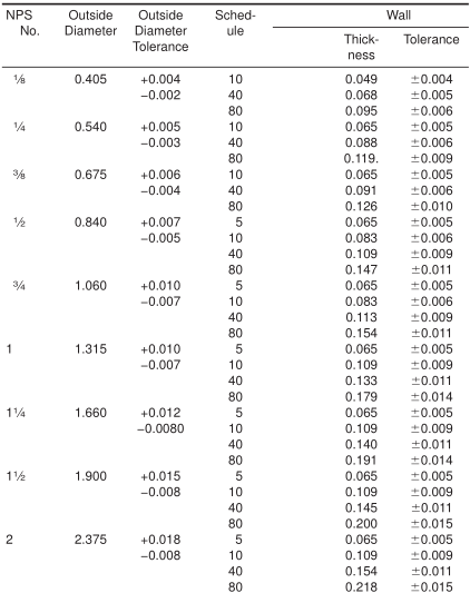
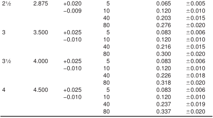
A All dimensions in inches.
2. Referenced Documents
2.1 ASTM Standards:
A 262 Practices for Detecting Susceptibility to Intergranular Attack in Austenitic Stainless Steels
A 370 Test Methods and Definitions for Mechanical Testing of Steel Products
A 480/A 480M Specification for General Requirements for Flat-Rolled Stainless and Heat-Resisting Steel Plate,Sheet, and Strip
A 999/A 999M Specification for General Requirements for Alloy and Stainless Steel Pipe
E 381 Method of Macroetch Testing Steel Bars, Billets,Blooms, and Forgings
E 527 Practice for Numbering Metals and Alloys (UNS) 3
2.2 ANSI Standards:
B 1.20.1 Pipe Threads, General Purpose
B 36.10 Welded and Seamless Wrought Steel Pipe
B 36.19 Stainless Steel Pipe
2.3 ASME Boiler and Pressure Vessel Code:
Section VIII Division 1, Pressure Vessels
2.4 SAE Standard:
SAE J 1086 Practice for Numbering Metals and Alloys (UNS)
3. Ordering Information
3.1 Orders for material under this specification should include the following as required, to describe the desired material adequately:
3.1.1 Quantity (feet, centimetres, or number of lengths),
3.1.2 Name of material (austenitic steel pipe),
3.1.3 Class (1.3). If not specified by the purchaser, the producer shall have the option to furnish either single-welded (SW) or double-welded (DW) pipe,
3.1.4 Grade (Table 2),
3.1.5 Size (NPS or outside diameter and schedule number or average wall thickness),
3.1.6 Length (specific or random) (Section 10),
3.1.7 End finish (Section on Ends of Specification A 999/A 999M),
3.1.8 Optional requirements (Section 9), (Supplementary Requirements S1 to S8),
3.1.9 Test report required (Section on Certification of Specification A 999/A 999M),
3.1.10 Specification designation, and
3.1.11 Special requirements or exceptions to the specification.
4. Materials and Manufacture
4.1 Manufacture:
4.1.1 The pipe shall be made by a machine-welding or an automatic-welding process, welding from one or both sides and producing full penetration welds with no addition of filler metal in the welding operation.
4.1.2 Weld repairs, with the addition of compatible filler metal, may be made to the weld joint in accordance with the requirements of the section on Repair by Welding of Specification A 999/A 999M.
4.1.3 Prior to final heat treatment of the pipe, the weld bead must be cold-worked by methods such as forging, planishing,drawing, swaging or bead rolling so as to obtain a flush condition on the inside and outside of the pipe. Undercuts shall be limited to shallow rounded depressions of less than 0.005 in.[0.127 mm] deep on either the inside or outside surface of the pipe with no encroachment of the minimum permitted wall thickness.
4.1.4 The pipe shall be pickled free of scale. When bright annealing is used, pickling is not necessary.
4.2 Heat Treatment:
4.2.1 All pipe shall be furnished in the heat-treated condition. The heat-treatment procedure, except for H grades N 08367 and S 31254, shall consist of heating the pipe to a minimum temperature of 1900°F [1040°C] and quenching in water or rapidly cooling by other means.
4.2.2 All H grades shall be furnished in the solution-treated condition. The minimum solution treating temperature for Grades TP321H, TP347H, and TP348H shall be 2000°F [1100°C] and for Grades TP304H and TP316H, 1900°F [1040°C]. If the H grade is hot-rolled, the minimum solution treating temperatures for Grades TP321H, TP347H, and TP348H shall be 1925°F [1050°C] and for Grades TP304H and TP316H, 1900°F [1040°C].
4.2.3 The heat-treatment procedure for S 31254 shall consist of heating the pipe to a minimum temperature of 2100°F [1150°C] and quenching in water or rapidly cooling by other means.
4.2.4 UNS N 08367 should be solution annealed from 2025°F minimum followed by rapid quenching.
5. Chemical Composition
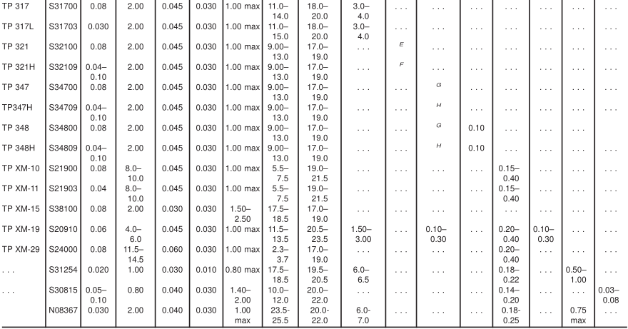
5.1 The steel shall conform to the chemical composition prescribed in Table 2.
5.2 When specified on the purchase order, a product analysis shall be supplied from one tube or coil of steel per heat. The product analysis tolerance of Specification A 480/A 480M shall apply.
TABLE 2 Chemical Requirements
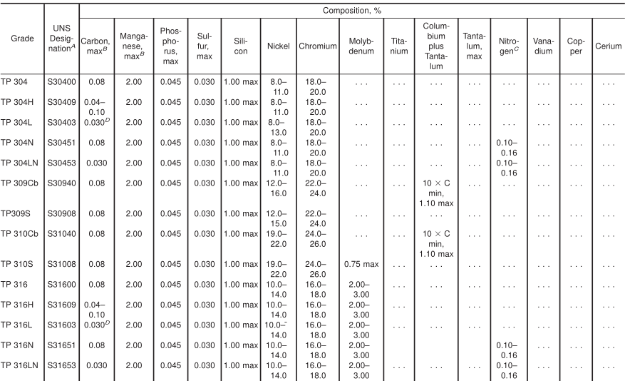
A New designation established in accordance with ASTM E 527 and SAE J1086.
B Maximum, unless otherwise indicated.
C The method of analysis for nitrogen shall be a matter of agreement between the purchaser and manufacturer.
D For small diameter or thin walls or both, where many drawing passes are required, a carbon maximum of 0.040 % is necessary in grades TP304L and TP316L. Small outside diameter tubes are defined as those less than 0.500 in. [12.7 mm] in outside diameter and light wall tubes as those less than 0.049 in. [1.2 mm] in average wall thickness (0.044 in. [1 mm] in minimum wall thickness).
E The titanium content shall be not less than five times the carbon content and not more than 0.70 %.
F The titanium content shall be not less than four times the carbon content and not more than 0.70 %.
G The columbium plus tantalum content shall be not less than ten times the carbon content and not more than 1.10 %.
H The columbium plus tantalum content shall be not less than eight times the carbon content and not more than 1.10 %.
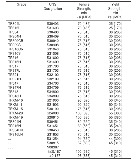
6. Tensile Requirements
6.1 The tensile properties of the material shall conform to the requirements prescribed in Table 3
TABLE 3 Tensile Requirements
7. Permissible Variations in Dimensions
7.1 Specified Diameter—The diameter at any point in each length of pipe shall be within the tolerance specified in Table 1.
7.2 Alignment (Camber)—Using a 3-ft [1.0-m] straightedge placed so that both ends are in contact with the pipe, the camber shall not be more than 0.030-in. [0.8-mm].
7.3 Thickness—The wall thickness at any point in the pipe shall be within the thickness tolerance specified in Table 3,except that for pipe in which the wall thickness exceeds 0.188-in. [4.8-mm] a weld reinforcement of up to 0.015-in.[0.38-mm] is permitted on the inside of the pipe.
8. Lengths
8.1 Pipe lengths shall be in accordance with the following regular practice.
8.1.1 Unless otherwise agreed upon, all sizes up to and including NPS 4 are available in a length up to 24 ft (Note 2)with the permissible range of 15 of 24 ft (Note 2).
NOTE 2—The value(s) applies when the inch-pound designation of this specification is the basis of purchase. When the “M” designation of this specification is the basis of purchase, the corresponding metric value(s) shall be agreed upon between the manufacturer and purchaser.
8.1.2 If definite cut lengths are desired, the lengths required shall be specified in the order. No pipe shall be under the specified length and not more than 1 ⁄ 4 in. [6 mm] over that specified.
8.1.3 No jointers are permitted unless otherwise specified.
9. Workmanship, Finish, and Appearance
9.1 The finished pipes shall be free of injurious imperfections and shall have a workmanlike finish. Minor imperfections may be removed by grinding, provided the wall thicknesses are not decreased to less than that permitted in Section 9.
10. General Requirements
10.1 Material furnished under this specification shall conform to the applicable requirements of the current edition of SpecificationA 999/A 999M unless otherwise provided herein.
11. Examination of Double-Welded Pipe
11.1 Both ends of each double-welded (Class DW) pipe shall be visually examined to determine that complete fusion was attained between the two welds. In lieu of examining the ends of the pipe, this examination may be performed on cropped ends removed from both ends of each double welded pipe.
12. Mechanical Tests Required
12.1 Transverse or Longitudinal Tension Test—One tension test shall be made on a specimen for lots of not more than 100 pipes. Tension tests shall be made on specimens from two tubes for lots of more than 100 pipes.
NOTE 3—The term “lot”, for mechanical tests, applies to all pipe of the same nominal size and wall thickness (or schedule) which is produced from the same heat of steel and subjected to the same finishing treatment
(1) in a continuous heat-treatment furnace, or (2) in a batch-type heat-treatment furnace, equipped with recording pyrometers and automatically controlled within a 50°F [30°C] range, the larger of (a) Each 200 ft [60 m] or fraction thereof or, (b) That pipe heat treated in the same batch furnace charge.
12.2 Flattening Test—For material heat treated in a batchtype furnace, flattening tests shall be made of 5 % of the pipe from each heat-treated lot. For material heat treated by the continuous process, this test shall be made on a sufficient number of pipe to constitute 5 % of the lot, but in no case less than two lengths of pipe.
12.2.1 For pipe where the diameter equals or exceeds NPS 10, a transverse-guided face bend test of the weld may be conducted instead of a flattening test in accordance with the method outlined in the steel tubular product supplement of Test Methods and Definitions A 370. The ductility of the weld shall be considered acceptable when there is no evidence of cracks in the weld or between the weld and the base metal after bending. Test specimens from 5 % of the lot shall be taken from the pipe or test plates of the same material as the pipe, the test plates being attached to the end of the cylinder and welded as a prolongation of the pipe longitudinal seam.
12.3 Hydrostatic Test—Each length of pipe shall be subjected to the hydrostatic test in accordance with Specification A 999/A 999M.
13. Product Marking
13.1 In addition to the marking specified in Specification A 999/A 999M, the marking shall include the manufac-turer’s identifying mark and double-welded pipe shall be identified with the mark (DW). For Grades TP304H, TP316H, TP321H,TP347H, TP348H, and S 30815, the marking shall also include the heat number and heat-treatment lot identification. If speci-fied in the purchase order, the marking for pipe larger than NPS 4 shall include the weight.