ASTM A813 Single-or Double-Welded Austenitic Stainless Pipe
ASTM A813/A813M
Standard Specification for Single- or Double-Welded Austenitic Stainless Steel Pipe
1. Scope*
1.1 This specification covers two classes of fit-up and alignment quality straight-seam single- or double-welded austenitic steel pipe intended for high-temperature and general corrosive service.
NOTE 1—When the impact test criterion for a low-temperature service would be 15 ft·lbf [20 J] energy absorption or 15 mils [0.38 mm] lateral expansion, some of the austenitic stainless steel grades covered by this specification are accepted by certain pressure vessel or piping codes without the necessity of making the actual test. For example, Grades 304,304L, and 347 are accepted by the ASME Pressure Vessel Code, Section VIII Division 1, and by the Chemical Plant and Refinery Piping Code,ANSI B31.3 for service at temperatures as low as −425 °F [−250 °C] without qualification by impact tests. Other AISI stainless steel grades are usually accepted for service temperatures as low as −325 °F [−200 °C] without impact testing. Impact testing may, under certain circumstances,be required. For example, materials with chromium or nickel content outside the AISI ranges, and for material with carbon content exceeding 0.10 %, are required to be impact tested under the rules ofASME Section VIII Division 1 when service temperatures are lower than −50 °F [−45 °C]
1.2 Grades TP304H, TP304N, TP316H, TP316N, TP321H,TP347H, and TP348H are modifications of Grades TP304,TP316, TP321, TP347,and TP348, and are intended for high-temperature service.
1.3 Two classes of pipe are covered as follows:
1.3.1 Class SW—Pipe, single-welded with no addition of filler metal and
1.3.2 Class DW—Pipe, double-welded with no addition of filler metal.
1.4 Optional supplementary requirements are provided for pipe where a greater degree of testing is desired. These supplementary requirements call for additional tests to be made and, when desired, one or more ofthese may be specified in the order.
1.5 Table 1 lists the dimensions of welded stainless steel pipe as shown in ANSI B36.19. Pipe having other dimensions may be furnished provided such pipe complies with all other requirements of this specification.
1.6 The values stated in either SI units or inch-pound units are to be regarded separately as standard. Within the text, the SI units are shown in brackets. The values stated in each system may not be exact equivalents; therefore, each system shall be used independently of the other. Combining values from the two systems may result in non-conformance with the standard. The inch-pound units shall apply unless the “M”designation of this specification is specified in the order.
A For pipe sizes not listed, the dimensions and tolerances shall be by agreement between the purchaser and producer.
B Schedules 5S and 10S wall thicknesses do not permit threading in accordance with the American National Standard for Pipe Threads (ANSI B1.20.1).
C These do not conform to the American National Standard for Welded and Seamless Wrought Steel Pipe (ANSI B36.10-1979).
2. Referenced Documents
2.1 ASTM Standards:
A262 Practices for Detecting Susceptibility to Intergranular Attack in Austenitic Stainless Steels
A370 Test Methods and Definitions for Mechanical Testing of Steel Products
A480/A480M Specification for General Requirements for Flat-Rolled Stainless and Heat-Resisting Steel Plate,Sheet, and Strip
A751 Test Methods, Practices, and Terminology for Chemical Analysis of Steel Products
A999/A999M Specification for General Requirements for Alloy and Stainless Steel Pipe
E213 Practice for Ultrasonic Testing of Metal Pipe and Tubing
E381 Method of Macroetch Testing Steel Bars, Billets,Blooms, and Forgings
E426 Practice for Electromagnetic (Eddy-Current) Examination of Seamless and Welded Tubular Products, Titanium,Austenitic Stainless Steel and Similar Alloys
E527 Practice for Numbering Metals and Alloys in the Unified Numbering System (UNS)
2.2 ANSI Standards:
B1.20.1 Pipe Threads, General Purpose
B31.3 Chemical Plant and Refinery Piping Code
B36.10 Welded and Seamless Wrought Steel Pipe
B36.19 Stainless Steel Pipe
2.3 ASME Boiler and Pressure Vessel Code:
Section VIII Division 1, Pressure Vessels
2.4 Other Standard:
SAE J1086 Practice for Numbering Metals and Alloys(UNS)
SNT-TC-1A Personnel Qualification and Certification in Nondestructive Testing
3. Ordering Information
3.1 Orders for material under this specification should include the following as required, to describe the desired material adequately:
3.1.1 Quantity (feet, centimetres, or number of lengths),
3.1.2 Name of material (austenitic steel pipe),
3.1.3 Class (1.3). If not specified by the purchaser, the producer shall have the option to furnish either single-welded (SW) or double-welded (DW) pipe,
3.1.4 Grade (Table 2),
3.1.5 Size (NPS or outside diameter and schedule number or average wall thickness),
3.1.6 Length (specific or random), (Section 9),
3.1.7 End finish (section on Ends of Specification A999/A999M),
3.1.8 Optional requirements (hydrostatic or nondestructive electric test, Section 13,) (Supplementary Requirements S1 to S6),
3.1.9 Test report required (Section on Certification of Specification A999/A999M),
3.1.10 Specification number, and
3.1.11 Special requirements or exceptions to the specification.
4. Materials and Manufacture
4.1 Manufacture:
4.1.1 The pipe shall be made by a machine-welding or an automatic-welding process, welding from one or both sides and producing full penetration welds with no addition of filler metal in the welding operation.
4.1.2 Weld repairs, with the addition of compatible filler metal, may be made to the weld joint in accordance with the requirements of the section on Repair by Welding of Specification A999/A999M.
4.1.3 The pipe shall be pickled free of scale. When bright annealing is used, pickling is not necessary.
4.2 Heat Treatment:
4.2.1 Except as provided in 4.2.6 and 4.2.7, all pipe shall be furnished in the heat-treated condition, except pipe sizes over NPS 6 may be furnished in the unheat-treated condition when specified in the order. When the pipe is furnished without final heat treatment, each pipe shall be marked HT-O and when a material test report for such pipe is furnished to the purchaser,the report shall indicate that the pipe has not been heat-treated.The heat-treatment procedure, except for H grades, N08367,and S31254, shall consist of heating the pipe to a minimum temperature of 1900 °F [1040 °C] and quenching in water or
rapidly cooling by other means.
4.2.2 All H grades shall be furnished in the solution-treated condition. If cold working is involved in processing, the minimum solution treating temperature for Grades TP321H,TP347H, and TP348H shall be 2000 °F [1100 °C] and for Grades TP304H and TP316H, 1900 °F [1040 °C]. If the H Grade is hot rolled, the minimum solution treating temperatures for Grades TP321H, TP347H, and TP348H shall be 1925
°F [1050 °C], and for Grades TP304H and TP316H, 1900 °F [1040 °C].
4.2.3 The heat-treatment procedure for S31254 shall consist ofheating the pipe to a minimum temperature of2100 °F [1150°C] and quenching in water or rapidly cooling by other means.
4.2.4 S31727 and S32053 shall be heat treated 1975 to 2155°F [1080 to 1180 °C] followed by quenching in water or rapidly cooling by other means.
4.2.5 UNS N08367 should be solution annealed from 2025°F [1107 °C] minimum followed by rapid quenching.
4.2.6 Except for H Grades and S31254, pipe sizes over NPS 6 may be furnished in the unheat-treated condition when specified in the order.
4.2.7 H Grades and S31254 in pipe sizes NPS 6 may be furnished in the unheat-treated condition when specified in the order, provided the heat treatment of 4.2.2 or 4.2.3, as applicable, is applied by the purchaser.
4.2.8 When the pipe is furnished without final heat treatment, each pipe shall be marked HT-O and when a material test report for such pipe is furnished to the purchaser,the report shall indicate that the pipe has not been heat-treated.
5. Chemical Composition
5.1 The steel shall conform to the chemical composition in Table 2.
5.2 When specified on the purchase order, a product analysis shall be supplied from one tube or coil ofsteel per heat. The product analysis tolerance of Specification A480/A480M shall apply.
6. Product Analysis
6.1 At the request ofthe purchaser, an analysis ofone length of flat-rolled stock from each heat, or one pipe from each lot shall be made by the manufacturer. A lot of pipe shall consist of the following number of lengths of the same size and wall thickness from any one heat of steel.
6.2 The results of these analyses shall be reported to the purchaser or his representative, and shall conform to the requirements specified in Section 5.
6.3 If the analysis of one of the tests specified in 6.1 does not conform to the requirements specified in Section 5, an analysis of each length of flat-rolled stock from each heat or pipe from the same heat or lot may be made, and all pipe conforming to the requirements shall be accepted.
6.4 For referee purposes, Test Methods, Practices, and Terminology A751 shall be used.
7. Tensile Requirements
7.1 The tensile properties of the material shall conform to the requirements prescribed in Table 3.
8. Permissible Variations in Dimensions
8.1 Permissible variations in dimensions shall not exceed the following at any point in each length of pipe.
8.1.1 Specified Diameter—The outside diameter shall be based on circumferential measurement and shall not exceed the tolerances stated as follows:
8.1.1.1 For sizes up to and including NPS 1 1 ⁄ 4 , 60.010 in.[60.25 mm],
8.1.1.2 For sizes NPS 1 1 ⁄ 2 up to and including NPS 6,60.020 in. [60.5 mm],
8.1.1.3 For sizes NPS 8 up to and including NPS 18,60.030 in. [60.75 mm],
8.1.1.4 For sizes NPS 20 up to and including NPS 24,60.040 in. [61 mm], and
8.1.1.5 For sizes NPS 30, 60.050 in. [61.25 mm].
8.1.1.6 Outside diameter tolerances closer than shown above may be obtained by agreement between the pipe manufacturer and purchaser.
8.1.2 Out-of-Roundness—The difference between the major and the minor outside diameter shall not be more than 1.5 % of the specified outside diameter.
8.1.3 Alignment (Camber)—Using a 10-ft [3.0-m] straightedge placed so that both ends are in contact with the pipe, the camber shall not be more than 3 ⁄ 16 in. [4.8 mm].
8.1.4 Thickness—The wall thickness at any point in the pipe excluding the weld, shall not be more than 12 % under or over the nominal thickness for wall thickness less than 0.188 in. [4.8mm] and not more than 0.030 in. [0.8 mm] under or over the nominal thickness for wall thickness 0.188 in. [4.8 mm] and greater. Weld reinforcement not to exceed 20 % of the wall thickness is permitted on each of the inside and outside surfaces of the pipe.
9. Lengths
9.1 Pipe lengths shall be in accordance with the following regular practice:
9.1.1 Unless otherwise agreed upon, all sizes up to and including NPS 8 are available in a length up to 24 ft (Note 2) with the permissible range of15 to 24 ft (Note 2). Short lengths are acceptable and the number and minimum length shall be agreed upon between the manufacturer and the purchaser.
NOTE 2—The value(s) applies when the inch-pound designation of this specification is the basis of purchase. When the “M” designation of this specification is the basis of purchase, the corresponding metric value(s) shall be agreed upon between the manufacturer and purchaser.
9.1.2 If definite cut lengths are desired, the lengths required shall be specified in the order. No pipe shall be under the specified length and not more than 1 ⁄ 4 in. [6 mm] over that specified.
10. Workmanship, Finish, and Appearance
10.1 The finished pipes shall be free of injurious imperfections and shall have a workmanlike finish. Minor imperfections may be removed by grinding, provided the wall thicknesses are not decreased to less than that permitted in Section 8.
11. Examination of Double-Welded Pipe
11.1 Both ends of each double-welded (Class DW) pipe shall be visually examined to determine that complete fusion was attained between the two welds. In lieu of examining the ends of the pipe, this examination may be performed on cropped ends removed from both ends of each double welded pipe.
12. Mechanical Tests Required
12.1 Transverse or Longitudinal Tension Test—One tension test shall be made on a specimen for lots of not more than 100 pipes. Tension tests shall be made on specimens from two tubes for lots of more than 100 pipes. Pipe size greater than NPS 6 shall be tested using the transverse tension test with the weld centered in the gauge length of the test specimen. Test specimens shall be taken from the pipe or test plates of the same material as the pipe, the test plates being attached to the end of the cylinder and welded as prolongation of the pipe longitudinal weld seam.
NOTE 3—The term lot, for mechanical tests, applies to all pipe of the same nominal size and wall thickness (or schedule) which is produced from the same heat of steel and subjected to the same finishing treatment:
(1) in a continuous heat-treatment furnace, or (2) in a batch-type heat-treatment furnace, equipped with recording pyrometers and automatically controlled within a 50 °F [30 °C] range, the larger of: (a) each 200 ft [60 m] or fraction thereof or (b) that pipe heat treated in the same batch furnace charge.
12.2 Flattening Test—For material heat treated in a batchtype furnace, flattening tests shall be made on 5 % of the pipe from each heat-treated lot. For material heat treated by the continuous process, this test shall be made on a sufficient number of pipe to constitute 5 % of the lot, but in no case less than two lengths of pipe.
12.2.1 For pipe where the diameter equals or exceeds NPS 10, a transverse-guided face bend test of the weld may be conducted instead of a flattening test in accordance with the method outlined in the steel tubular product supplement oTest Methods and Definitions A370. The ductility of the weld shall be considered acceptable when there is no evidence of cracks in the weld or between the weld and the base metal after bending. Test specimens from 5 % of the lot shall be taken from the pipe or test plates ofthe same material as the pipe, the test plates being attached to the end of the cylinder and welded as a prolongation of the pipe longitudinal seam.
13. Hydrostatic or Nondestructive Electric Test
13.1 Each pipe shall be subjected to the nondestructive electric test or the hydrostatic test. The type of test to be used shall be at the option of the manufacturer, unless otherwise specified in the purchase order.
13.2 The hydrostatic test shall be in accordance with Specification A999/A999M.
13.3 Nondestructive Examination—Each pipe shall be examined with a nondestructive test in accordance with Practice E213, or E426. Unless specifically called out by the purchaser,the selection of the nondestructive electric test will be at the option ofthe manufacturer. The range ofpipe sizes that may be examined by each method shall be subject to the limitations in the scope of the respective practices.
13.3.1 The following information is for the benefit of the user of this specification:
13.3.1.1 The reference standards defined in 13.9.1 – 13.9.4 are convenient standards for calibration of nondestructive testing equipment. The dimensions of these standards should not be construed as the minimum size imperfection detectable by such equipment.
13.3.1.2 The ultrasonic testing (UT) can be performed to detect both longitudinally and circumferentially oriented defects. It should be recognized that different techniques should be employed to detect differently oriented imperfections. The examination may not detect short, deep, defects.
13.3.1.3 The eddy-current testing (ET) referenced in this specification, (Practice E426), has the capability of detecting significant discontinuities, especially the short abrupt type.
13.3.1.4 A purchaser interested in ascertaining the nature (type, size, location, and orientation) ofdiscontinuities that can be detected in the specific application of these examinations should discuss this with the manufacturer of the tubular product.
13.4 Time ofExamination:
13.4.1 Nondestructive testing for specification acceptance shall be performed after all mechanical processing, heat treatments, and straightening operations. This requirement does not preclude additional testing at earlier stages in the processing.
13.5 Surface Condition:
13.5.1 All surfaces shall be free of scale, dirt, grease, paint, or other foreign material that could interfere with interpretation oftest results. The methods used for cleaning and preparing the surfaces for examination shall not be detrimental to the base metal or the surface finish.
13.5.2 Excessive surface roughness or deep scratches can produce signals that interfere with the test.
13.6 Extent ofExamination:
13.6.1 The relative motion ofthe pipe and the transducer(s),coil(s), or sensor(s) shall be such that the entire pipe surface is scanned, except as in 13.5.2.
13.6.2 The existence of end effects is recognized, and the extent of such effects shall be determined by the manufacturer, and, if requested, shall be reported to the purchaser. Other nondestructive tests may be applied to the end areas, subject to agreement between the purchaser and the manufacturer.
13.7 Operator Qualifications:
13.7.1 The test unit operator shall be certified in accordance with SNT-TC-1A, or an equivalent recognized and documented standard.
13.8 Test Conditions:
13.8.1 For eddy-current testing, the excitation coil frequency shall be chosen to ensure adequate penetration yet provide good signal-to-noise ratio.
13.8.2 The maximum eddy-current coil frequency used shall be as follows:
On specified walls up to 0.050 in.—100 KHz max
On specified walls up to 0.150 in.—50 KHz max
On specified walls above 0.150 in.—10 KHz max
13.8.3 Ultrasonic—For examination by the ultrasonic method, the minimum nominal transducer frequency shall be 2.00 MHz and the maximum nominal transducer size shall be 1.5 in.
(1) If the equipment contains a reject notice filter setting,this shall remain off during calibration and testing unless linearity can be demonstrated at that setting.
13.9 Reference Standards:
13.9.1 Reference standards of convenient length shall be prepared from a length ofpipe ofthe same grade, size (NPS, or outside diameter and schedule or wall thickness), surface finish and heat treatment condition as the pipe to be examined.
13.9.2 For Ultrasonic Testing, the reference ID and OD notches shall be any one of the three common notch shapes shown in Practice E213, at the option of the manufacturer. The depth of each notch shall not exceed 12 1 ⁄ 2 % of the specified nominal wall thickness of the pipe or 0.004 in., whichever is greater. The width of the notch shall not exceed twice the depth. Notches shall be placed on both the OD and ID surfaces.
13.9.3 For Eddy-Current Testing, the reference standard shall contain, at the option of the manufacturer, any one of the following discontinuities:
(1) Drilled Hole—The reference standard shall contain three or more holes, equally spaced circumferentially around the pipe and longitudinally separated by a sufficient distance to allow distinct identification of the signal from each hole. The holes shall be drilled radially and completely through the pipe wall, with care being taken to avoid distortion ofthe pipe while drilling. One hole shall be drilled in the weld, if visible.Alternately, the producer of welded pipe may choose to drill one hole in the weld and run the calibration standard through the test coils three times with the weld turned at 120° on each pass. The hole diameter shall vary with NPS as follows:
(2) Transverse Tangential Notch—Using a round tool or file with a
1 ⁄ 4 in. [6.4 mm] diameter, a notch shall be filed or milled tangential to the surface and transverse to the longitudinal axis of the pipe. Said notch shall have a depth not exceeding 12 1 ⁄ 2 % of the specified nominal wall thickness of the pipe or 0.004 in. (0.102 mm), whichever is greater.
(3) Longitudinal Notch—A notch 0.031 in. or less in width shall be machined in a radial plane parallel to the tube axis on the outside surface of the pipe, to have a depth not exceeding 12 1 ⁄ 2 % of the specified wall thickness of the pipe or 0.004 in.,whichever is greater. The length of the notch shall be compatible with the testing method.
13.9.4 More or smaller reference discontinuities, or both,may be used by agreement between the purchaser and the manufacturer.
13.10 Standardization Procedure:
13.10.1 The test apparatus shall be standardized at the beginning and end of each series of pipes of the same size (NPS or diameter and schedule or wall thickness), Grade and heat treatment condition, and at intervals not exceeding 4 h.More frequent standardization may be performed at the manufacturer’s option or may be required upon agreement between the purchaser and the manufacturer.
13.10.2 The test apparatus shall also be standardized after any change in test system settings, change of operator, equipment repair, or interruption due to power loss, process shutdown or when a problem is suspected.
13.10.3 The reference standard shall be passed through the test apparatus at the same speed and test system settings as the pipe to be tested.
13.10.4 The signal-to-noise ratio for the reference standard shall be 2 1 ⁄ 2 to 1 or greater. Extraneous signals caused by dentifiable causes such as dings, scratches, dents, straightener marks, etc., shall not be considered noise. The rejection amplitude shall be adjusted to be at least 50 % of full scale of the readout display.
13.10.5 If upon any standardization, the rejection amplitude has decreased by 29 % (3 dB) of peak height from the last standardization, the pipe since the last calibration shall be rejected. The test system settings may be changed, or the transducer(s), coil(s) or sensor(s) adjusted, and the unit restandardized, but all pipe tested since the last acceptable standardization must be retested for acceptance.
13.11 Evaluation ofImperfections:
13.11.1 Pipes producing a signal equal to or greater than the lowest signal produced by the reference standard(s) shall be identified and separated from the acceptable pipes. The area producing the signal may be reexamined.
13.11.2 Such pipes shall be rejected if the test signal was produced by imperfections that cannot be identified or was produced by cracks or crack-like imperfections. These pipes may be repaired per Sections 4 and 10. To be accepted, a repaired pipe must pass the same non-destructive test by which it was rejected, and it must meet the minimum wall thickness requirements of this specification.
13.11.3 If the test signals were produced by visual imperfections such as:
(1) Scratches,
(2) Surface roughness,
(3) Dings,
(4) Straightener marks,
(5) Cutting chips,
(6) Steel die stamps,
(7) Stop marks, or
(8) Pipe reducer ripple.
The pipe may be accepted based on visual examination provided the imperfection is less than 0.004 in. [0.1 mm] or 12 1 ⁄ 2 % of the specified wall thickness (whichever is greater).
13.11.4 Rejected pipe may be reconditioned and retested providing the wall thickness is not decreased to less than that required by this or the product specification. The outside diameter at the point ofgrinding may be reduced by the amount so removed. To be accepted, retested pipe shall meet the test requirement.
13.11.5 If the imperfection is explored to the extent that it can be identified as non-rejectable, the pipe may be accepted without further test providing the imperfection does not encroach on the minimum wall thickness.
14. Product Marking
14.1 In addition to that specified in Specification A999/A999M, the marking shall include the manufacturer’s private identifying mark and identified as either single welded (SW) or double welded (DW) as applicable. For Grades TP304H,TP316H, TP321H, TP347H, and TP348H, the marking shall also include the heat number and heat-treatment lot identification. If specified in the purchase order, the marking for pipe larger than NPS 4 shall include the weights.
14.2 When heat treatment of the pipe is not performed, the pipe shall be marked HT-O.
14.3 When a hydrostatic test of the pipe is not performed,the pipe shall be marked NH.
15. General Requirements
15.1 Material furnished under this specification shall conform to the applicable requirements of the current edition of Specification A999/A999M unless otherwise provided herein.
Standard Specification for Single- or Double-Welded Austenitic Stainless Steel Pipe
1. Scope*
1.1 This specification covers two classes of fit-up and alignment quality straight-seam single- or double-welded austenitic steel pipe intended for high-temperature and general corrosive service.
NOTE 1—When the impact test criterion for a low-temperature service would be 15 ft·lbf [20 J] energy absorption or 15 mils [0.38 mm] lateral expansion, some of the austenitic stainless steel grades covered by this specification are accepted by certain pressure vessel or piping codes without the necessity of making the actual test. For example, Grades 304,304L, and 347 are accepted by the ASME Pressure Vessel Code, Section VIII Division 1, and by the Chemical Plant and Refinery Piping Code,ANSI B31.3 for service at temperatures as low as −425 °F [−250 °C] without qualification by impact tests. Other AISI stainless steel grades are usually accepted for service temperatures as low as −325 °F [−200 °C] without impact testing. Impact testing may, under certain circumstances,be required. For example, materials with chromium or nickel content outside the AISI ranges, and for material with carbon content exceeding 0.10 %, are required to be impact tested under the rules ofASME Section VIII Division 1 when service temperatures are lower than −50 °F [−45 °C]
1.2 Grades TP304H, TP304N, TP316H, TP316N, TP321H,TP347H, and TP348H are modifications of Grades TP304,TP316, TP321, TP347,and TP348, and are intended for high-temperature service.
1.3 Two classes of pipe are covered as follows:
1.3.1 Class SW—Pipe, single-welded with no addition of filler metal and
1.3.2 Class DW—Pipe, double-welded with no addition of filler metal.
1.4 Optional supplementary requirements are provided for pipe where a greater degree of testing is desired. These supplementary requirements call for additional tests to be made and, when desired, one or more ofthese may be specified in the order.
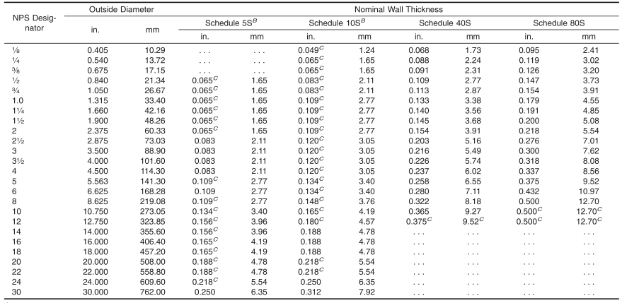
1.5 Table 1 lists the dimensions of welded stainless steel pipe as shown in ANSI B36.19. Pipe having other dimensions may be furnished provided such pipe complies with all other requirements of this specification.
1.6 The values stated in either SI units or inch-pound units are to be regarded separately as standard. Within the text, the SI units are shown in brackets. The values stated in each system may not be exact equivalents; therefore, each system shall be used independently of the other. Combining values from the two systems may result in non-conformance with the standard. The inch-pound units shall apply unless the “M”designation of this specification is specified in the order.
TABLE 1 Dimensions of Welded and Seamless Stainless Steel Pipe A
A For pipe sizes not listed, the dimensions and tolerances shall be by agreement between the purchaser and producer.
B Schedules 5S and 10S wall thicknesses do not permit threading in accordance with the American National Standard for Pipe Threads (ANSI B1.20.1).
C These do not conform to the American National Standard for Welded and Seamless Wrought Steel Pipe (ANSI B36.10-1979).
2. Referenced Documents
2.1 ASTM Standards:
A262 Practices for Detecting Susceptibility to Intergranular Attack in Austenitic Stainless Steels
A370 Test Methods and Definitions for Mechanical Testing of Steel Products
A480/A480M Specification for General Requirements for Flat-Rolled Stainless and Heat-Resisting Steel Plate,Sheet, and Strip
A751 Test Methods, Practices, and Terminology for Chemical Analysis of Steel Products
A999/A999M Specification for General Requirements for Alloy and Stainless Steel Pipe
E213 Practice for Ultrasonic Testing of Metal Pipe and Tubing
E381 Method of Macroetch Testing Steel Bars, Billets,Blooms, and Forgings
E426 Practice for Electromagnetic (Eddy-Current) Examination of Seamless and Welded Tubular Products, Titanium,Austenitic Stainless Steel and Similar Alloys
E527 Practice for Numbering Metals and Alloys in the Unified Numbering System (UNS)
2.2 ANSI Standards:
B1.20.1 Pipe Threads, General Purpose
B31.3 Chemical Plant and Refinery Piping Code
B36.10 Welded and Seamless Wrought Steel Pipe
B36.19 Stainless Steel Pipe
2.3 ASME Boiler and Pressure Vessel Code:
Section VIII Division 1, Pressure Vessels
2.4 Other Standard:
SAE J1086 Practice for Numbering Metals and Alloys(UNS)
SNT-TC-1A Personnel Qualification and Certification in Nondestructive Testing
3. Ordering Information
3.1 Orders for material under this specification should include the following as required, to describe the desired material adequately:
3.1.1 Quantity (feet, centimetres, or number of lengths),
3.1.2 Name of material (austenitic steel pipe),
3.1.3 Class (1.3). If not specified by the purchaser, the producer shall have the option to furnish either single-welded (SW) or double-welded (DW) pipe,
3.1.4 Grade (Table 2),
3.1.5 Size (NPS or outside diameter and schedule number or average wall thickness),
3.1.6 Length (specific or random), (Section 9),
3.1.7 End finish (section on Ends of Specification A999/A999M),
3.1.8 Optional requirements (hydrostatic or nondestructive electric test, Section 13,) (Supplementary Requirements S1 to S6),
3.1.9 Test report required (Section on Certification of Specification A999/A999M),
3.1.10 Specification number, and
3.1.11 Special requirements or exceptions to the specification.
4. Materials and Manufacture
4.1 Manufacture:
4.1.1 The pipe shall be made by a machine-welding or an automatic-welding process, welding from one or both sides and producing full penetration welds with no addition of filler metal in the welding operation.
4.1.2 Weld repairs, with the addition of compatible filler metal, may be made to the weld joint in accordance with the requirements of the section on Repair by Welding of Specification A999/A999M.
4.1.3 The pipe shall be pickled free of scale. When bright annealing is used, pickling is not necessary.
4.2 Heat Treatment:
4.2.1 Except as provided in 4.2.6 and 4.2.7, all pipe shall be furnished in the heat-treated condition, except pipe sizes over NPS 6 may be furnished in the unheat-treated condition when specified in the order. When the pipe is furnished without final heat treatment, each pipe shall be marked HT-O and when a material test report for such pipe is furnished to the purchaser,the report shall indicate that the pipe has not been heat-treated.The heat-treatment procedure, except for H grades, N08367,and S31254, shall consist of heating the pipe to a minimum temperature of 1900 °F [1040 °C] and quenching in water or
rapidly cooling by other means.
4.2.2 All H grades shall be furnished in the solution-treated condition. If cold working is involved in processing, the minimum solution treating temperature for Grades TP321H,TP347H, and TP348H shall be 2000 °F [1100 °C] and for Grades TP304H and TP316H, 1900 °F [1040 °C]. If the H Grade is hot rolled, the minimum solution treating temperatures for Grades TP321H, TP347H, and TP348H shall be 1925
°F [1050 °C], and for Grades TP304H and TP316H, 1900 °F [1040 °C].
4.2.3 The heat-treatment procedure for S31254 shall consist ofheating the pipe to a minimum temperature of2100 °F [1150°C] and quenching in water or rapidly cooling by other means.
4.2.4 S31727 and S32053 shall be heat treated 1975 to 2155°F [1080 to 1180 °C] followed by quenching in water or rapidly cooling by other means.
4.2.5 UNS N08367 should be solution annealed from 2025°F [1107 °C] minimum followed by rapid quenching.
4.2.6 Except for H Grades and S31254, pipe sizes over NPS 6 may be furnished in the unheat-treated condition when specified in the order.
4.2.7 H Grades and S31254 in pipe sizes NPS 6 may be furnished in the unheat-treated condition when specified in the order, provided the heat treatment of 4.2.2 or 4.2.3, as applicable, is applied by the purchaser.
4.2.8 When the pipe is furnished without final heat treatment, each pipe shall be marked HT-O and when a material test report for such pipe is furnished to the purchaser,the report shall indicate that the pipe has not been heat-treated.
5. Chemical Composition
5.1 The steel shall conform to the chemical composition in Table 2.
5.2 When specified on the purchase order, a product analysis shall be supplied from one tube or coil ofsteel per heat. The product analysis tolerance of Specification A480/A480M shall apply.
6. Product Analysis
6.1 At the request ofthe purchaser, an analysis ofone length of flat-rolled stock from each heat, or one pipe from each lot shall be made by the manufacturer. A lot of pipe shall consist of the following number of lengths of the same size and wall thickness from any one heat of steel.
| NPS Number | Lengths of Pipe in Lot |
| Under 2 | 400 or fraction thereof |
| 2 to 5 inclusive | 200 or fraction thereof |
| 6 and over | 100 or fraction thereof |
6.2 The results of these analyses shall be reported to the purchaser or his representative, and shall conform to the requirements specified in Section 5.
6.3 If the analysis of one of the tests specified in 6.1 does not conform to the requirements specified in Section 5, an analysis of each length of flat-rolled stock from each heat or pipe from the same heat or lot may be made, and all pipe conforming to the requirements shall be accepted.
6.4 For referee purposes, Test Methods, Practices, and Terminology A751 shall be used.
7. Tensile Requirements
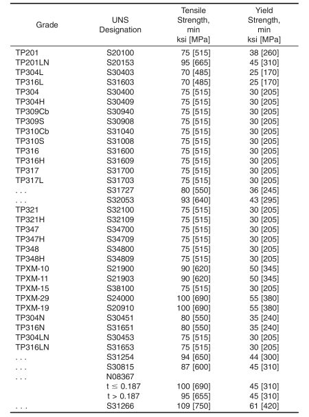
7.1 The tensile properties of the material shall conform to the requirements prescribed in Table 3.
TABLE 3 Tensile Requirements
8. Permissible Variations in Dimensions
8.1 Permissible variations in dimensions shall not exceed the following at any point in each length of pipe.
8.1.1 Specified Diameter—The outside diameter shall be based on circumferential measurement and shall not exceed the tolerances stated as follows:
8.1.1.1 For sizes up to and including NPS 1 1 ⁄ 4 , 60.010 in.[60.25 mm],
8.1.1.2 For sizes NPS 1 1 ⁄ 2 up to and including NPS 6,60.020 in. [60.5 mm],
8.1.1.3 For sizes NPS 8 up to and including NPS 18,60.030 in. [60.75 mm],
8.1.1.4 For sizes NPS 20 up to and including NPS 24,60.040 in. [61 mm], and
8.1.1.5 For sizes NPS 30, 60.050 in. [61.25 mm].
8.1.1.6 Outside diameter tolerances closer than shown above may be obtained by agreement between the pipe manufacturer and purchaser.
8.1.2 Out-of-Roundness—The difference between the major and the minor outside diameter shall not be more than 1.5 % of the specified outside diameter.
8.1.3 Alignment (Camber)—Using a 10-ft [3.0-m] straightedge placed so that both ends are in contact with the pipe, the camber shall not be more than 3 ⁄ 16 in. [4.8 mm].
8.1.4 Thickness—The wall thickness at any point in the pipe excluding the weld, shall not be more than 12 % under or over the nominal thickness for wall thickness less than 0.188 in. [4.8mm] and not more than 0.030 in. [0.8 mm] under or over the nominal thickness for wall thickness 0.188 in. [4.8 mm] and greater. Weld reinforcement not to exceed 20 % of the wall thickness is permitted on each of the inside and outside surfaces of the pipe.
9. Lengths
9.1 Pipe lengths shall be in accordance with the following regular practice:
9.1.1 Unless otherwise agreed upon, all sizes up to and including NPS 8 are available in a length up to 24 ft (Note 2) with the permissible range of15 to 24 ft (Note 2). Short lengths are acceptable and the number and minimum length shall be agreed upon between the manufacturer and the purchaser.
NOTE 2—The value(s) applies when the inch-pound designation of this specification is the basis of purchase. When the “M” designation of this specification is the basis of purchase, the corresponding metric value(s) shall be agreed upon between the manufacturer and purchaser.
9.1.2 If definite cut lengths are desired, the lengths required shall be specified in the order. No pipe shall be under the specified length and not more than 1 ⁄ 4 in. [6 mm] over that specified.
10. Workmanship, Finish, and Appearance
10.1 The finished pipes shall be free of injurious imperfections and shall have a workmanlike finish. Minor imperfections may be removed by grinding, provided the wall thicknesses are not decreased to less than that permitted in Section 8.
11. Examination of Double-Welded Pipe
11.1 Both ends of each double-welded (Class DW) pipe shall be visually examined to determine that complete fusion was attained between the two welds. In lieu of examining the ends of the pipe, this examination may be performed on cropped ends removed from both ends of each double welded pipe.
12. Mechanical Tests Required
12.1 Transverse or Longitudinal Tension Test—One tension test shall be made on a specimen for lots of not more than 100 pipes. Tension tests shall be made on specimens from two tubes for lots of more than 100 pipes. Pipe size greater than NPS 6 shall be tested using the transverse tension test with the weld centered in the gauge length of the test specimen. Test specimens shall be taken from the pipe or test plates of the same material as the pipe, the test plates being attached to the end of the cylinder and welded as prolongation of the pipe longitudinal weld seam.
NOTE 3—The term lot, for mechanical tests, applies to all pipe of the same nominal size and wall thickness (or schedule) which is produced from the same heat of steel and subjected to the same finishing treatment:
(1) in a continuous heat-treatment furnace, or (2) in a batch-type heat-treatment furnace, equipped with recording pyrometers and automatically controlled within a 50 °F [30 °C] range, the larger of: (a) each 200 ft [60 m] or fraction thereof or (b) that pipe heat treated in the same batch furnace charge.
12.2 Flattening Test—For material heat treated in a batchtype furnace, flattening tests shall be made on 5 % of the pipe from each heat-treated lot. For material heat treated by the continuous process, this test shall be made on a sufficient number of pipe to constitute 5 % of the lot, but in no case less than two lengths of pipe.
12.2.1 For pipe where the diameter equals or exceeds NPS 10, a transverse-guided face bend test of the weld may be conducted instead of a flattening test in accordance with the method outlined in the steel tubular product supplement oTest Methods and Definitions A370. The ductility of the weld shall be considered acceptable when there is no evidence of cracks in the weld or between the weld and the base metal after bending. Test specimens from 5 % of the lot shall be taken from the pipe or test plates ofthe same material as the pipe, the test plates being attached to the end of the cylinder and welded as a prolongation of the pipe longitudinal seam.
13. Hydrostatic or Nondestructive Electric Test
13.1 Each pipe shall be subjected to the nondestructive electric test or the hydrostatic test. The type of test to be used shall be at the option of the manufacturer, unless otherwise specified in the purchase order.
13.2 The hydrostatic test shall be in accordance with Specification A999/A999M.
13.3 Nondestructive Examination—Each pipe shall be examined with a nondestructive test in accordance with Practice E213, or E426. Unless specifically called out by the purchaser,the selection of the nondestructive electric test will be at the option ofthe manufacturer. The range ofpipe sizes that may be examined by each method shall be subject to the limitations in the scope of the respective practices.
13.3.1 The following information is for the benefit of the user of this specification:
13.3.1.1 The reference standards defined in 13.9.1 – 13.9.4 are convenient standards for calibration of nondestructive testing equipment. The dimensions of these standards should not be construed as the minimum size imperfection detectable by such equipment.
13.3.1.2 The ultrasonic testing (UT) can be performed to detect both longitudinally and circumferentially oriented defects. It should be recognized that different techniques should be employed to detect differently oriented imperfections. The examination may not detect short, deep, defects.
13.3.1.3 The eddy-current testing (ET) referenced in this specification, (Practice E426), has the capability of detecting significant discontinuities, especially the short abrupt type.
13.3.1.4 A purchaser interested in ascertaining the nature (type, size, location, and orientation) ofdiscontinuities that can be detected in the specific application of these examinations should discuss this with the manufacturer of the tubular product.
13.4 Time ofExamination:
13.4.1 Nondestructive testing for specification acceptance shall be performed after all mechanical processing, heat treatments, and straightening operations. This requirement does not preclude additional testing at earlier stages in the processing.
13.5 Surface Condition:
13.5.1 All surfaces shall be free of scale, dirt, grease, paint, or other foreign material that could interfere with interpretation oftest results. The methods used for cleaning and preparing the surfaces for examination shall not be detrimental to the base metal or the surface finish.
13.5.2 Excessive surface roughness or deep scratches can produce signals that interfere with the test.
13.6 Extent ofExamination:
13.6.1 The relative motion ofthe pipe and the transducer(s),coil(s), or sensor(s) shall be such that the entire pipe surface is scanned, except as in 13.5.2.
13.6.2 The existence of end effects is recognized, and the extent of such effects shall be determined by the manufacturer, and, if requested, shall be reported to the purchaser. Other nondestructive tests may be applied to the end areas, subject to agreement between the purchaser and the manufacturer.
13.7 Operator Qualifications:
13.7.1 The test unit operator shall be certified in accordance with SNT-TC-1A, or an equivalent recognized and documented standard.
13.8 Test Conditions:
13.8.1 For eddy-current testing, the excitation coil frequency shall be chosen to ensure adequate penetration yet provide good signal-to-noise ratio.
13.8.2 The maximum eddy-current coil frequency used shall be as follows:
On specified walls up to 0.050 in.—100 KHz max
On specified walls up to 0.150 in.—50 KHz max
On specified walls above 0.150 in.—10 KHz max
13.8.3 Ultrasonic—For examination by the ultrasonic method, the minimum nominal transducer frequency shall be 2.00 MHz and the maximum nominal transducer size shall be 1.5 in.
(1) If the equipment contains a reject notice filter setting,this shall remain off during calibration and testing unless linearity can be demonstrated at that setting.
13.9 Reference Standards:
13.9.1 Reference standards of convenient length shall be prepared from a length ofpipe ofthe same grade, size (NPS, or outside diameter and schedule or wall thickness), surface finish and heat treatment condition as the pipe to be examined.
13.9.2 For Ultrasonic Testing, the reference ID and OD notches shall be any one of the three common notch shapes shown in Practice E213, at the option of the manufacturer. The depth of each notch shall not exceed 12 1 ⁄ 2 % of the specified nominal wall thickness of the pipe or 0.004 in., whichever is greater. The width of the notch shall not exceed twice the depth. Notches shall be placed on both the OD and ID surfaces.
13.9.3 For Eddy-Current Testing, the reference standard shall contain, at the option of the manufacturer, any one of the following discontinuities:
(1) Drilled Hole—The reference standard shall contain three or more holes, equally spaced circumferentially around the pipe and longitudinally separated by a sufficient distance to allow distinct identification of the signal from each hole. The holes shall be drilled radially and completely through the pipe wall, with care being taken to avoid distortion ofthe pipe while drilling. One hole shall be drilled in the weld, if visible.Alternately, the producer of welded pipe may choose to drill one hole in the weld and run the calibration standard through the test coils three times with the weld turned at 120° on each pass. The hole diameter shall vary with NPS as follows:
| NPS Designator | Hole Diameter |
| 1 ⁄ 2 | 0.039 in. [1 mm] |
| above 1 ⁄ 2 to 1 1 ⁄ 4 | 0.055 in. [1.4 mm] |
| above 1 1 ⁄ 4 to 2 | 0.071 in. [1.8 mm] |
| above 2 to 5 | 0.087 in. [2.2 mm] |
| above 5 | 0.106 in. [2.7 mm] |
(2) Transverse Tangential Notch—Using a round tool or file with a
1 ⁄ 4 in. [6.4 mm] diameter, a notch shall be filed or milled tangential to the surface and transverse to the longitudinal axis of the pipe. Said notch shall have a depth not exceeding 12 1 ⁄ 2 % of the specified nominal wall thickness of the pipe or 0.004 in. (0.102 mm), whichever is greater.
(3) Longitudinal Notch—A notch 0.031 in. or less in width shall be machined in a radial plane parallel to the tube axis on the outside surface of the pipe, to have a depth not exceeding 12 1 ⁄ 2 % of the specified wall thickness of the pipe or 0.004 in.,whichever is greater. The length of the notch shall be compatible with the testing method.
13.9.4 More or smaller reference discontinuities, or both,may be used by agreement between the purchaser and the manufacturer.
13.10 Standardization Procedure:
13.10.1 The test apparatus shall be standardized at the beginning and end of each series of pipes of the same size (NPS or diameter and schedule or wall thickness), Grade and heat treatment condition, and at intervals not exceeding 4 h.More frequent standardization may be performed at the manufacturer’s option or may be required upon agreement between the purchaser and the manufacturer.
13.10.2 The test apparatus shall also be standardized after any change in test system settings, change of operator, equipment repair, or interruption due to power loss, process shutdown or when a problem is suspected.
13.10.3 The reference standard shall be passed through the test apparatus at the same speed and test system settings as the pipe to be tested.
13.10.4 The signal-to-noise ratio for the reference standard shall be 2 1 ⁄ 2 to 1 or greater. Extraneous signals caused by dentifiable causes such as dings, scratches, dents, straightener marks, etc., shall not be considered noise. The rejection amplitude shall be adjusted to be at least 50 % of full scale of the readout display.
13.10.5 If upon any standardization, the rejection amplitude has decreased by 29 % (3 dB) of peak height from the last standardization, the pipe since the last calibration shall be rejected. The test system settings may be changed, or the transducer(s), coil(s) or sensor(s) adjusted, and the unit restandardized, but all pipe tested since the last acceptable standardization must be retested for acceptance.
13.11 Evaluation ofImperfections:
13.11.1 Pipes producing a signal equal to or greater than the lowest signal produced by the reference standard(s) shall be identified and separated from the acceptable pipes. The area producing the signal may be reexamined.
13.11.2 Such pipes shall be rejected if the test signal was produced by imperfections that cannot be identified or was produced by cracks or crack-like imperfections. These pipes may be repaired per Sections 4 and 10. To be accepted, a repaired pipe must pass the same non-destructive test by which it was rejected, and it must meet the minimum wall thickness requirements of this specification.
13.11.3 If the test signals were produced by visual imperfections such as:
(1) Scratches,
(2) Surface roughness,
(3) Dings,
(4) Straightener marks,
(5) Cutting chips,
(6) Steel die stamps,
(7) Stop marks, or
(8) Pipe reducer ripple.
The pipe may be accepted based on visual examination provided the imperfection is less than 0.004 in. [0.1 mm] or 12 1 ⁄ 2 % of the specified wall thickness (whichever is greater).
13.11.4 Rejected pipe may be reconditioned and retested providing the wall thickness is not decreased to less than that required by this or the product specification. The outside diameter at the point ofgrinding may be reduced by the amount so removed. To be accepted, retested pipe shall meet the test requirement.
13.11.5 If the imperfection is explored to the extent that it can be identified as non-rejectable, the pipe may be accepted without further test providing the imperfection does not encroach on the minimum wall thickness.
14. Product Marking
14.1 In addition to that specified in Specification A999/A999M, the marking shall include the manufacturer’s private identifying mark and identified as either single welded (SW) or double welded (DW) as applicable. For Grades TP304H,TP316H, TP321H, TP347H, and TP348H, the marking shall also include the heat number and heat-treatment lot identification. If specified in the purchase order, the marking for pipe larger than NPS 4 shall include the weights.
14.2 When heat treatment of the pipe is not performed, the pipe shall be marked HT-O.
14.3 When a hydrostatic test of the pipe is not performed,the pipe shall be marked NH.
15. General Requirements
15.1 Material furnished under this specification shall conform to the applicable requirements of the current edition of Specification A999/A999M unless otherwise provided herein.