ASTM A771/A771M Stainless Steel Tube
ASTM A 771/A 771M
Standard Specification for Seamless Austenitic and Martensitic Stainless Steel Tubing for Liquid Metal-Cooled Reactor Core Components
1. Scope
1.1 This specification covers seamless annealed or cold-worked, austenitic or martensitic stainless steel tubing of0.100 to 1.0 in. [2.5 to 25 mm] outside diameter with wall thickness of 0.050 in. [1.3 mm] or less for use at high temperature in liquid metal-cooled reactor plants.
1.2 The values stated in either inch-pound units or SI units are to be regarded separately as standard. Within the text, the SI units are shown in brackets. The values stated in each system are not exact equivalents; therefore, each system must be used independently ofthe other. Combining values from the two systems may result in nonconformance with the specification.
1.3 This specification and the applicable material specifications are expressed in both inch-pound and SI units. However,unless the order specifies the applicable “M” specification designation (SI units), the material shall be furnished in inch-pound units.
2. Referenced Documents
2.1 ASTM Standards:
A 370 Test Methods and Definitions for Mechanical Testing of Steel Products 2,3
A 380 Practice for Cleaning, Descaling and Passivation of Stainless Steel Parts, Equipment, and Systems
A 450/A 450M Specification for General Requirements for Carbon, Ferritic Alloy, and Austenitic Alloy Steel Tubes
D 129 Test Method for Sulfur in Petroleum Products (General Bomb Method)
D 808 Test Method for Chlorine in New and Used Petroleum Products (Bomb Method) 4
E 3 Methods of Preparation of Metallographic Specimens
E 21 Test Methods for Elevated Temperature Tension Tests of Metallic Materials
E 45 Test Methods for Determining the Inclusion Content of Steel 5
E 165 Test Method for Liquid Penetrant Examination
E 213 Practice for Ultrasonic Examination of Metal Pipe and Tubing 6
E 384 Test Method for Microhardness of Materials
E 407 Practice for Microetching Metals and Alloys
2.2 ANSI Standard:
B46.1 Surface Texture
2.3 ASNT Standard:
SNT-TC-1A Recommended Practice for Nondestructive Testing Personnel Qualification and Certification
2.4 ASME Standard:
NQA-1 Quality Assurance Program Requirements for Nuclear Facilities
3. Ordering Information
3.1 It is the responsibility of the purchaser to specify all requirements that are necessary for the safe and satisfactory performance of material ordered under this specification.Examples of such requirements include but are not limited to the following:
3.1.1 Quantity (feet, metres, or number of lengths),
3.1.2 Name of material (seamless tubes),
3.1.3 Grade (Table 1),
3.1.4 Annealing and tempering requirements for martensitic grades,
3.1.5 Condition (cold-worked, annealed, or thermomechanical condition),
3.1.6 Dimensions:
3.1.6.1 Diameter and length (tubing dimensions or applicable drawings),
3.1.6.2 Ovality (tolerances on roundness),
3.1.6.3 Wall thickness and eccentricity,
3.1.6.4 Straightness,
3.1.7 Tubing end configuration,
3.1.8 Percent of cold work,
3.1.9 Number of tension tests and tensile properties at other cold-work levels,
3.1.10 Packaging,
3.1.11 Surface roughness,
3.1.12 Grain size,
3.1.13 Identification,
3.1.14 Surface condition, and
3.1.15 Sampling levels.
4. General Requirements for Delivery
4.1 Material supplied under this specification shall conform to the applicable requirements of Specification A 450/ A 450M unless otherwise specified herein.
5. Manufacture
5.1 Melting—The steel shall be made by a double-vacuum melting process. Unless an alternative melting process has been approved in writing by the purchaser, the process shall consist of a vacuum induction melt followed by a consumable electrode vacuum-arc remelt. Additions of rare earths during melting are prohibited unless approved by the purchaser.
5.2 Tubemaking—Tubing shall be made by a seamless process. Tubemaking processes shall have been previously qualified as acceptable. Free sinking to final size is prohibited.There shall be no drawing “chatter” and straightener “ripples” and other process variables that affect nondestructive examination. Surface-finishing processes, such as belt polishing and other mechanical conditioning of the finished tubing, are prohibited. Any in-process conditioning procedures shall be approved prior to use. Chemical pickling of tubing (in-process and finished) is not permitted unless approved by the purchaser prior to use.
5.3 Special Handling—Handling methods shall minimize tube-to-tube contact during processing, cleaning, annealing,and storage, and shall be consistent with the preservation of a mar-free surface finish. Special handling procedures shall beprovided to maintain the identity of tubing at all times. The manufacturer shall submit his proposed handling methods to the purchaser for approval prior to use.
5.4 Heat Treating:
5.4.1 Austenitic Grades—All annealing operations shall be performed by use of the continuous bright-hydrogen annealing process unless otherwise specified by the purchaser. The dew point of the gas at the hydrogen inlet shall be less than −80°F [−62°C], and the dew point of the hydrogen at exit shall not exceed −40°F [−40°C]. The temperature and time shall be selected to ensure carbide solution. The temperature ofthe final anneal shall be demonstrated by thermocouple readings during furnace profile measurements with the thermocouple on the inside of tubes ½ in. [13 mm] or larger and on the outside of smaller tubes. Cooling shall be at a rate rapid enough to avoid visible carbide precipitation as described in 10.5 unless a
specific thermomechanical treatment is specified in Section 3.
5.4.2 Martensitic Grades—Martensitic grades shall be annealed and tempered as specified in the order.
5.5 Condition—Tubing shall be furnished in the annealed,cold-worked, or thermomechanical condition as specified in Section 3.
5.6 Cold Work—Cold-worked tubing shall be plug drawn subsequent to the final bright anneal. Percent cold work shall be as specified in Section 3 and shall be based upon the reduction in transverse area or change in weight per unit length. Cold-worked tubing shall be cold-drawn to finished size and delivered without further heat treatment.
5.6.1 Cold-Work Determination—Calculate percent cold work determined by reduction in transverse area at each end and center of selected tubes as follows:
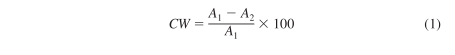
where:
CW = percent cold work,
A 1 = tubing cross-sectional area prior to final cold draw, and
A 2 = tubing cross-sectional area after final cold draw.Cross-sectional area shall be based upon average diameter at each location.
5.6.2 Calculate percent cold work determined by change in weight per unit length as follows:
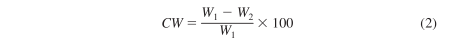
where:
CW = percent cold work,
W 1 = weight per unit length of tubing prior to final cold draw, and
W 2 = weight per unit length oftubing after final cold draw.
5.6.3 The cold-draw procedure and method for measuring percent cold work shall be submitted to the purchaser for review and approval prior to use.
5.7 Lot Size—Tube lots shall be limited to a maximum of 5000 ft [1500 m] of the same nominal size, produced from the same heat, fabricated by the same reduction sequence, cold-reduced in the same manner, and annealed in the same annealing charge (or produced in one continuous run if annealed in a continuous furnace).
5.8 Identification—Tubes shall be marked to assure individual tube identity and processed in a manner that will maintain traceability back to the heat. The supplier shall identify individual cladding tubes with a lot code and a sequential number as specified in Section 3. The numbering system shall be designed to identify manufacturer, lot, and tube number. Tubes shall be marked using electrolytic etching techniques approved by the purchaser.
6. Chemical Composition
6.1 Finished tubing shall conform to the requirements as to chemical composition prescribed in Table 1. Ingots shall be analyzed and the results shall be reported to the purchaser for information prior to fabrication.
A Aim for 0.25.
7. Mechanical Properties
7.1 Tensile Properties—Tensile properties of finished annealed or cold-worked Type 316 and cold-worked S 38660 stainless steel tubing tested at room temperature and at 1000°F [538°C] shall meet the requirements in Table 2. Tensile properties offinished tubing ofother grades and conditions and the number of tests shall be as specified in Section 3.
7.2 Hardness—Vickers microhardness tests shall be performed on each lot of the finished cold-worked tubing. Hardness shall be 220 to 290 using a 0.5-kgf load (231 to 304 HK).Microhardness shall be measured on mounted and polished tube samples of full cross section, by procedures described in Test Method E 384. At least six indentations per sample shall be taken with the indents comprising a traverse across the tube wall thickness. The number oftubes tested in each lot shall not be less than the number of tension tests required.
A 20 percent cold-worked.
8. Dimensions
8.1 Diameter, Length, and End Configuration—Diameter,length, and end configuration for the finished tubing shall be as specified in Section 3.
8.2 Ovality—Tubing ovality shall be as specified in Section 3.
8.3 Wall Thickness and Eccentricity—The wall thickness and eccentricity of finished tubing shall be as specified in Section 3. The maximum acceptable eccentricity of tube hollows shall be 5 % of the nominal wall thickness. Eccentricity of intermediate sizes between the tube hollow and the finished tubing, resulting from mechanical conditioning to remove surface defects, shall not exceed 5 % of the nominal wall thickness at that size.
8.4 Straightness—The tubing shall be free of bends or kinks, and the straightness shall be as specified in Section 3 or the applicable drawing. Final hand straightening shall not be permitted unless approved by the purchaser.
9. Surface Requirements
9.1 Surface Condition—The finished tubing shall be free of visible oxide, scale, splits, laps, cracks, seams, protrusions, gall marks, inclusions and other defects of a kind and to the extent specified in Section 3. Finished tubing shall exhibit an asdrawn finish and shall not be conditioned by surface grinding,belt sanding, or other mechanical processes.
9.2 Surface Roughness, Tube Hollows—Tube hollow surface roughness shall not exceed 63 µin. [1.6 µm] arithmetic average (ANSI B46.1).
9.3 Surface Roughness, Finished Tubing—Finished tubing external surfaces and samples of internal surfaces shall not exceed the surface roughness specified in Section 3 and shall be free of scratches, dents, scuff marks, or pitting that exceeds 0.001 in. [0.025 mm] in depth.
9.4 Cleaning—Finished tubing shall be cleaned in nitric acid prior to final inspection tests. Cleaning shall be in accordance with Practice A 380 using a 20 to 40 volume % nitric acid solution at room temperature. Tubes shall be thoroughly rinsed in 0.25 MV-cm deionized water, and dried.
10. Additional Test Requirements
10.1 Where lot qualification is listed, the lot shall be accepted only when all ofthe required number ofsamples meet the referenced requirements. Sampling levels shall be as specified in Section 3. Referenced test methods are the preferred methods. Actual methods used shall be equal to or better than the methods referenced and shall be approved by the purchaser prior to use.
10.2 Grain Size—The grain size of tubing material following the final anneal and prior to cold drawing shall be as specified in Section 3.
10.3 Inclusions—The inclusion content of the hot-worked bar shall not exceed the limits set forth in Table 3 when determined by Practice E 45, Microscope Method D, except that 35 % of the total fields rated may exhibit inclusion levels up to a rating of1 for Types A, B, C, and D combined and 3 % of the total fields rated may exhibit inclusion levels up to a rating of 1 1 ⁄ 2 for Types A, B, C, and D combined. Complex carbides shall not be classified as inclusions.
10.4 Intergranular Attack—Finished tubing shall be metallographically examined at 1003 to verify freedom from intergranular attack.
10.5 Carbide Precipitation—Finished tubing shall be metallographically examined to verify freedom from visible carbide precipitation after heat treatment specified in 5.4 unless specific thermomechanical treatments are specified by the purchaser to control carbide precipitates. A transverse section ofthe tubing shall be mounted, polished, etched, and examined at 5003. Specimen preparation shall be as described in Methods E 3 using etching procedure 13 prescribed in Table 2 of Practice E 407.
10.6 Equipment /Technique Accuracy—Dimensional measurements shall be made with a device measuring in units no greater than 10 % of the specified tolerance range. For limits specified as minimum or maximum use a device measuring in units to one decimal place beyond the character specified.Alternative measuring equipment shall require approval by the purchaser.
11. Nondestructive Examination
11.1 Penetrant Examination, Tube Hollows—Tube hollows shall be examined on their external and internal surfaces in accordance with the requirements of Procedures A-1, A-2, or B-2 of Test Method E 165 and shall be free of indications as specified in the order. The penetrant materials shall be analyzed for sulfur and halogen in accordance with Test Methods D 129 and D 808. The residual amount ofsulfur and ofhalogens shall not exceed 1 ⁄2 weight % (0.005).
11.2 Ultrasonic Examination—Each tube shall be ultrasoni-cally examined in accordance with Practice E 213 and the added requirements contained herein. Procedures shall be approved by the purchaser prior to use. Examination shall be made in both circumferential and both longitudinal directions.
11.2.1 Calibrate the standard notch dimensions as follows:
Depth (% of wall thickness)—3 %
Minimum depth—0.001 in. [0.025 mm]
Maximum length—0.030 in. [0.76 mm]
Maximum width—the minimum practical, but not greater than twice the depth
11.2.2 In addition to the longitudinal reference notches described in Section 8 of Practice E 213 and 11.2.1 above,transverse notches of the above dimensions shall be placed on the inner and outer surfaces of the calibration standard at the locations described in Practice E 213.
11.2.3 Actual notch dimensions of the standard shall be determined by measurement ofnegative replicas ofthe notches using photomicrographic techniques.
11.2.4 Equipment shall be calibrated employing a translation feed helix of the transducer, with respect to the tube, such that a clearly discernible response is obtained from each reference notch on at least three successive revolutions of the tube.
11.2.5 A permanent recording of each test trace shall be made.
11.2.6 All nondestructive testing personnel shall be qualified and perform in accordance with SNT-TC-1A.
12. Acceptance Criteria, Lot Basis Tests
12.1 In the event of failure of a test required by 7.1, 7.2,10.2, 10.4, 10.5, the entire lot of tubes represented by the test shall be rejected except as follows:
12.1.1 The tube lots represented by the tests of 7.1, 7.2,10.2, or 10.5 may be reprocessed and retested. Retesting shall include all tests and examinations previously passed, up to the time of failure, and twice the number of tubes per lot shall be tested.
12.1.2 Instead ofthe alternative actions permitted by 12.1.1,each tube may be tested individually for acceptance where this can be done without destroying the tube with respect to other requirements.
13. Cleanliness
13.1 Finished tubing shall be free of scale, nondestructive examination residue, metallic particles, oil, grease, lubricants,residual cleaning compounds, dirt, chips, and other such extraneous material.
13.2 Contact preservatives shall not be used.
14. Preparation for Delivery
14.1 Packaging—Each tube length shall be inserted in a transparent polyethylene plastic sleeve sealed at one end only and packaged as specified in Section 3 to maintain conformance with this standard.
14.2 Shipping Containers—A complete description of shipping containers for tubing shall be submitted to the purchaser for approval before being used.
14.3 Marking—Each packing box shall be legibly and conspicuously marked with the following data:
Purchase order number,
Specification number,
Name of supplier,
Size,
Lot number,
Number of pieces in container,
Number of feet (or pieces) in lot, and
Gross and net weights.
14.4 Records—Records showing complete fabrication sequence from melt through drawing, annealing, and cold work,shall be maintained for each tube lot. Records shall include, but are not limited to, the number and types of reduction by tube reducer, plug draw or rod draw, the sequence of such operations indicating the tube size at each reduction, the sequence of annealing operations detailing the time, temperature, and atmosphere or the annealing cycle, and grain size of annealed material. The manufacturer shall supply such information with his test reports on all delivered tubing.
15. Quality Assurance Program
15.1 The materials manufacturer shall be responsible for establishing and maintaining a quality system program in order to control the quality during manufacture, testing, examination,repair, and treatment of the material, including subcontracted services, to assure that all materials supplied by him conform to the requirements of the specification. Compliance with ASME NQA-1 may be accepted as compliance with this section. The program shall be documented in a Quality System Manual that shall be implemented by procedures that are maintained by the materials manufacturer. The program shall be subject to audit and shall include the following:
15.1.1 Organization—The authority and responsibilities of personnel in charge of the quality system program shall be clearly established and be independent of the individual or group performing the specific manufacturing activity.
15.1.2 Manufacturing Control—The materials manufacturer shall operate under a controlled system such as process sheets, shop procedures, check lists, travelers, or equivalent procedures.
15.1.3 Calibration of Measuring and Test Equipment—Procedures shall be in effect to assure that tools, gages,instruments, and other measuring, testing, and examination equipment and devices used to verify compliance of material with the basic material specification and this specification are calibrated, controlled, adjusted and maintained to assure accuracy within the specified limits. Calibration shall be against measurement standards that have known valid relationship to National Standards, where such standards exist. When discrepancies are found at calibration, which significantly affect the
measurement of material specification properties, corrective action is required. Methods for resolution of these discrepancies shall be part of the quality system program.
15.1.4 Control of Nondestructive Examination Procedures—All nondestructive examinations required shall be performed in accordance with detailed written procedures that are capable ofdetecting and locating unacceptable discontinuities. Qualification of personnel performing or interpreting nondestructive examination, or both, shall be in accordance with SNT-TC-1A, supplements and appendixes, as applicable,for the technique and methods used. Written procedures and records shall be made available to the purchaser on request. At least one copy of the procedure shall be available to nondestructive examination personnel for reference on request.
15.1.5 Procedural controls ofheat treatment for all materials and materials test coupons shall be maintained and implemented.
15.1.6 Nonconforming Material shall be identified and reviewed for acceptance, rejection, repair, or rework in accordance with documented procedures. The responsibility and authority for the disposition of nonconforming material shall be defined. Repaired and reworked material shall be reexamined in accordance with applicable procedures. Conditions adverse to final product quality such as malfunctions,deficiencies, deviations, defective material and equipment and nonconformances shall be promptly identified and reported to appropriate levels of the materials manufacturer’s management. The identification, cause of condition, and corrective
action taken, shall be documented.
15.1.7 Audits—Planned and periodic audits by personnel not having direct responsibility in the areas being audited shall be performed to assure compliance with the quality system program. Written procedures or checklists shall be used.Follow-up action including reaudit of deficient areas, shall be taken where indicated.
15.1.8 Identification and Control ofMaterials—Procedural controls for identification of materials including partially processed materials shall assure that identification is maintained either on the material or on records traceable to the material throughout manufacture.
16. Responsibility
16.1 Unless otherwise specified, the manufacturer shall be responsible for the performance of all tests and inspections required prior to offering any tubing for acceptance. The performance of such tests and inspections shall not limit the right of the purchaser to conduct such other tests and inspections as necessary to ensure that all tubing is in conformance with all requirements of this specification. Unless otherwise specified, the manufacturer may use either his or any commercial laboratory acceptable to the purchaser. Records of all tests and examinations shall be kept complete, current, and available to the purchaser for periodic examination during manufacturing processes.
17. Certification
17.1 The material manufacturer’s certificate of compliance certifying that the material was manufactured, tested, and examined in accordance with this specification and any added requirements of the purchase order shall be furnished at the time of shipment, together with a report of the results of all required tests, and examinations. Certifications, tests, and examination reports shall be positively relatable to the materials represented.
18. Keywords
18.1 austenitic stainless steel; nuclear applications; stainless steel tubing; steel tubing
Standard Specification for Seamless Austenitic and Martensitic Stainless Steel Tubing for Liquid Metal-Cooled Reactor Core Components
1. Scope
1.1 This specification covers seamless annealed or cold-worked, austenitic or martensitic stainless steel tubing of0.100 to 1.0 in. [2.5 to 25 mm] outside diameter with wall thickness of 0.050 in. [1.3 mm] or less for use at high temperature in liquid metal-cooled reactor plants.
1.2 The values stated in either inch-pound units or SI units are to be regarded separately as standard. Within the text, the SI units are shown in brackets. The values stated in each system are not exact equivalents; therefore, each system must be used independently ofthe other. Combining values from the two systems may result in nonconformance with the specification.
1.3 This specification and the applicable material specifications are expressed in both inch-pound and SI units. However,unless the order specifies the applicable “M” specification designation (SI units), the material shall be furnished in inch-pound units.
2. Referenced Documents
2.1 ASTM Standards:
A 370 Test Methods and Definitions for Mechanical Testing of Steel Products 2,3
A 380 Practice for Cleaning, Descaling and Passivation of Stainless Steel Parts, Equipment, and Systems
A 450/A 450M Specification for General Requirements for Carbon, Ferritic Alloy, and Austenitic Alloy Steel Tubes
D 129 Test Method for Sulfur in Petroleum Products (General Bomb Method)
D 808 Test Method for Chlorine in New and Used Petroleum Products (Bomb Method) 4
E 3 Methods of Preparation of Metallographic Specimens
E 21 Test Methods for Elevated Temperature Tension Tests of Metallic Materials
E 45 Test Methods for Determining the Inclusion Content of Steel 5
E 165 Test Method for Liquid Penetrant Examination
E 213 Practice for Ultrasonic Examination of Metal Pipe and Tubing 6
E 384 Test Method for Microhardness of Materials
E 407 Practice for Microetching Metals and Alloys
2.2 ANSI Standard:
B46.1 Surface Texture
2.3 ASNT Standard:
SNT-TC-1A Recommended Practice for Nondestructive Testing Personnel Qualification and Certification
2.4 ASME Standard:
NQA-1 Quality Assurance Program Requirements for Nuclear Facilities
3. Ordering Information
3.1 It is the responsibility of the purchaser to specify all requirements that are necessary for the safe and satisfactory performance of material ordered under this specification.Examples of such requirements include but are not limited to the following:
3.1.1 Quantity (feet, metres, or number of lengths),
3.1.2 Name of material (seamless tubes),
3.1.3 Grade (Table 1),
3.1.4 Annealing and tempering requirements for martensitic grades,
3.1.5 Condition (cold-worked, annealed, or thermomechanical condition),
3.1.6 Dimensions:
3.1.6.1 Diameter and length (tubing dimensions or applicable drawings),
3.1.6.2 Ovality (tolerances on roundness),
3.1.6.3 Wall thickness and eccentricity,
3.1.6.4 Straightness,
3.1.7 Tubing end configuration,
3.1.8 Percent of cold work,
3.1.9 Number of tension tests and tensile properties at other cold-work levels,
3.1.10 Packaging,
3.1.11 Surface roughness,
3.1.12 Grain size,
3.1.13 Identification,
3.1.14 Surface condition, and
3.1.15 Sampling levels.
4. General Requirements for Delivery
4.1 Material supplied under this specification shall conform to the applicable requirements of Specification A 450/ A 450M unless otherwise specified herein.
5. Manufacture
5.1 Melting—The steel shall be made by a double-vacuum melting process. Unless an alternative melting process has been approved in writing by the purchaser, the process shall consist of a vacuum induction melt followed by a consumable electrode vacuum-arc remelt. Additions of rare earths during melting are prohibited unless approved by the purchaser.
5.2 Tubemaking—Tubing shall be made by a seamless process. Tubemaking processes shall have been previously qualified as acceptable. Free sinking to final size is prohibited.There shall be no drawing “chatter” and straightener “ripples” and other process variables that affect nondestructive examination. Surface-finishing processes, such as belt polishing and other mechanical conditioning of the finished tubing, are prohibited. Any in-process conditioning procedures shall be approved prior to use. Chemical pickling of tubing (in-process and finished) is not permitted unless approved by the purchaser prior to use.
5.3 Special Handling—Handling methods shall minimize tube-to-tube contact during processing, cleaning, annealing,and storage, and shall be consistent with the preservation of a mar-free surface finish. Special handling procedures shall beprovided to maintain the identity of tubing at all times. The manufacturer shall submit his proposed handling methods to the purchaser for approval prior to use.
5.4 Heat Treating:
5.4.1 Austenitic Grades—All annealing operations shall be performed by use of the continuous bright-hydrogen annealing process unless otherwise specified by the purchaser. The dew point of the gas at the hydrogen inlet shall be less than −80°F [−62°C], and the dew point of the hydrogen at exit shall not exceed −40°F [−40°C]. The temperature and time shall be selected to ensure carbide solution. The temperature ofthe final anneal shall be demonstrated by thermocouple readings during furnace profile measurements with the thermocouple on the inside of tubes ½ in. [13 mm] or larger and on the outside of smaller tubes. Cooling shall be at a rate rapid enough to avoid visible carbide precipitation as described in 10.5 unless a
specific thermomechanical treatment is specified in Section 3.
5.4.2 Martensitic Grades—Martensitic grades shall be annealed and tempered as specified in the order.
5.5 Condition—Tubing shall be furnished in the annealed,cold-worked, or thermomechanical condition as specified in Section 3.
5.6 Cold Work—Cold-worked tubing shall be plug drawn subsequent to the final bright anneal. Percent cold work shall be as specified in Section 3 and shall be based upon the reduction in transverse area or change in weight per unit length. Cold-worked tubing shall be cold-drawn to finished size and delivered without further heat treatment.
5.6.1 Cold-Work Determination—Calculate percent cold work determined by reduction in transverse area at each end and center of selected tubes as follows:
where:
CW = percent cold work,
A 1 = tubing cross-sectional area prior to final cold draw, and
A 2 = tubing cross-sectional area after final cold draw.Cross-sectional area shall be based upon average diameter at each location.
5.6.2 Calculate percent cold work determined by change in weight per unit length as follows:
where:
CW = percent cold work,
W 1 = weight per unit length of tubing prior to final cold draw, and
W 2 = weight per unit length oftubing after final cold draw.
5.6.3 The cold-draw procedure and method for measuring percent cold work shall be submitted to the purchaser for review and approval prior to use.
5.7 Lot Size—Tube lots shall be limited to a maximum of 5000 ft [1500 m] of the same nominal size, produced from the same heat, fabricated by the same reduction sequence, cold-reduced in the same manner, and annealed in the same annealing charge (or produced in one continuous run if annealed in a continuous furnace).
5.8 Identification—Tubes shall be marked to assure individual tube identity and processed in a manner that will maintain traceability back to the heat. The supplier shall identify individual cladding tubes with a lot code and a sequential number as specified in Section 3. The numbering system shall be designed to identify manufacturer, lot, and tube number. Tubes shall be marked using electrolytic etching techniques approved by the purchaser.
6. Chemical Composition
6.1 Finished tubing shall conform to the requirements as to chemical composition prescribed in Table 1. Ingots shall be analyzed and the results shall be reported to the purchaser for information prior to fabrication.
TABLE 1 Alloy Composition Limits for Austenitic Stainless Steel Tubing
| Grade UNS Designation | TP 31 6 | . . . | . . . |
| S31 600 | S38660 | S421 00 | |
| Element | Weight, % | ||
| Carbon | 0.040–0.060 | 0.030–0.050 | 0.1 7–0.23 |
| Manganese | 1 .00–2.00 | 1 .65–2.35 | 0.40–0.70 |
| Phosphorus, max | 0.040 | 0.040 | 0.040 |
| Sulfur, max | 0.01 0 | 0.01 0 | 0.01 0 |
| Silicon | 0.50–0.75 | 0.50–1 .00 | 0.20–0.30 |
| Nickel | 1 3.0–1 4.0 | 1 4.5–1 6.5 | 0.30–0.80 |
| Chromium | 1 7.0–1 8.0 | 1 2.5–1 4.5 | 11 .0–1 2.5 |
| Molybdenum | 2.00–3.00 | 1 .50–2.50 | 0.80–1 .20 |
| Titanium | . . . | 0.1 0–0.40 A | . . . |
| Columbium, max | 0.050 | 0.050 | 0.050 max |
| Tantalum, max | 0.020 | 0.020 | . . . |
| Tungsten | . . . | . . . | 0.40–0.60 |
| Nitrogen, max | 0.01 0 | 0.005 | . . . |
| Aluminum, max | 0.050 | 0.050 | 0.050 |
| Arsenic, max | 0.030 | 0.030 | . . . |
| Boron, max | 0.0020 | 0.0020 | . . . |
| Cobalt, max | 0.050 | 0.050 | . . . |
| Copper, max | 0.04 | 0.04 | . . . |
| Vanadium, max | 0.05 | 0.05 | 0.25–0.35 |
A Aim for 0.25.
7. Mechanical Properties
7.1 Tensile Properties—Tensile properties of finished annealed or cold-worked Type 316 and cold-worked S 38660 stainless steel tubing tested at room temperature and at 1000°F [538°C] shall meet the requirements in Table 2. Tensile properties offinished tubing ofother grades and conditions and the number of tests shall be as specified in Section 3.
7.2 Hardness—Vickers microhardness tests shall be performed on each lot of the finished cold-worked tubing. Hardness shall be 220 to 290 using a 0.5-kgf load (231 to 304 HK).Microhardness shall be measured on mounted and polished tube samples of full cross section, by procedures described in Test Method E 384. At least six indentations per sample shall be taken with the indents comprising a traverse across the tube wall thickness. The number oftubes tested in each lot shall not be less than the number of tension tests required.
TABLE 2 Tensile Requirements—Austenitic Stainless Steel Tubing
| Alloy | Test Temperature | Tensile Strength, ksi [MPa] | Yield Strength, ksi [MPa] | Minimum Total Elongation, % |
| TP 31 6 | room | 75–1 00 [51 7–689] | 30–50 [207–345] | 40 |
| 1 000°F [538°C] | 55–70 [379–483] | 1 5–30 [1 03–207] | 30 | |
| TP 31 6 A | room | 11 0–1 25 [758–862] | 80–11 0 [552–758] | 15 |
| 1 000°F [538°C] | 75–1 00 [51 7–689] | 60–85 [41 4–586] | 5 | |
| S38660 A | room | 95–1 20 [655–827] | 75–11 0 [51 7–758] | 10 |
| 1 000°F [538°C] | 70–1 00 [483–689] | 60–85 [41 4–586] | 5 |
A 20 percent cold-worked.
8. Dimensions
8.1 Diameter, Length, and End Configuration—Diameter,length, and end configuration for the finished tubing shall be as specified in Section 3.
8.2 Ovality—Tubing ovality shall be as specified in Section 3.
8.3 Wall Thickness and Eccentricity—The wall thickness and eccentricity of finished tubing shall be as specified in Section 3. The maximum acceptable eccentricity of tube hollows shall be 5 % of the nominal wall thickness. Eccentricity of intermediate sizes between the tube hollow and the finished tubing, resulting from mechanical conditioning to remove surface defects, shall not exceed 5 % of the nominal wall thickness at that size.
8.4 Straightness—The tubing shall be free of bends or kinks, and the straightness shall be as specified in Section 3 or the applicable drawing. Final hand straightening shall not be permitted unless approved by the purchaser.
9. Surface Requirements
9.1 Surface Condition—The finished tubing shall be free of visible oxide, scale, splits, laps, cracks, seams, protrusions, gall marks, inclusions and other defects of a kind and to the extent specified in Section 3. Finished tubing shall exhibit an asdrawn finish and shall not be conditioned by surface grinding,belt sanding, or other mechanical processes.
9.2 Surface Roughness, Tube Hollows—Tube hollow surface roughness shall not exceed 63 µin. [1.6 µm] arithmetic average (ANSI B46.1).
9.3 Surface Roughness, Finished Tubing—Finished tubing external surfaces and samples of internal surfaces shall not exceed the surface roughness specified in Section 3 and shall be free of scratches, dents, scuff marks, or pitting that exceeds 0.001 in. [0.025 mm] in depth.
9.4 Cleaning—Finished tubing shall be cleaned in nitric acid prior to final inspection tests. Cleaning shall be in accordance with Practice A 380 using a 20 to 40 volume % nitric acid solution at room temperature. Tubes shall be thoroughly rinsed in 0.25 MV-cm deionized water, and dried.
10. Additional Test Requirements
10.1 Where lot qualification is listed, the lot shall be accepted only when all ofthe required number ofsamples meet the referenced requirements. Sampling levels shall be as specified in Section 3. Referenced test methods are the preferred methods. Actual methods used shall be equal to or better than the methods referenced and shall be approved by the purchaser prior to use.
10.2 Grain Size—The grain size of tubing material following the final anneal and prior to cold drawing shall be as specified in Section 3.
10.3 Inclusions—The inclusion content of the hot-worked bar shall not exceed the limits set forth in Table 3 when determined by Practice E 45, Microscope Method D, except that 35 % of the total fields rated may exhibit inclusion levels up to a rating of1 for Types A, B, C, and D combined and 3 % of the total fields rated may exhibit inclusion levels up to a rating of 1 1 ⁄ 2 for Types A, B, C, and D combined. Complex carbides shall not be classified as inclusions.
10.4 Intergranular Attack—Finished tubing shall be metallographically examined at 1003 to verify freedom from intergranular attack.
10.5 Carbide Precipitation—Finished tubing shall be metallographically examined to verify freedom from visible carbide precipitation after heat treatment specified in 5.4 unless specific thermomechanical treatments are specified by the purchaser to control carbide precipitates. A transverse section ofthe tubing shall be mounted, polished, etched, and examined at 5003. Specimen preparation shall be as described in Methods E 3 using etching procedure 13 prescribed in Table 2 of Practice E 407.
10.6 Equipment /Technique Accuracy—Dimensional measurements shall be made with a device measuring in units no greater than 10 % of the specified tolerance range. For limits specified as minimum or maximum use a device measuring in units to one decimal place beyond the character specified.Alternative measuring equipment shall require approval by the purchaser.
TABLE 3 Inclusion Content Limits
| Inclusion Type | |||||||
| Sulfide Type (A) | Alumina Type (B) | Silicate Type (C) | Globular Oxide (D) | ||||
| Thin | Heavy | Thin | Heavy | Thin | Heavy | Thin | Heavy |
| 1/2 | 0 | 0 | 0 | 0 | 0 | 1/2 | 1/2 |
11. Nondestructive Examination
11.1 Penetrant Examination, Tube Hollows—Tube hollows shall be examined on their external and internal surfaces in accordance with the requirements of Procedures A-1, A-2, or B-2 of Test Method E 165 and shall be free of indications as specified in the order. The penetrant materials shall be analyzed for sulfur and halogen in accordance with Test Methods D 129 and D 808. The residual amount ofsulfur and ofhalogens shall not exceed 1 ⁄2 weight % (0.005).
11.2 Ultrasonic Examination—Each tube shall be ultrasoni-cally examined in accordance with Practice E 213 and the added requirements contained herein. Procedures shall be approved by the purchaser prior to use. Examination shall be made in both circumferential and both longitudinal directions.
11.2.1 Calibrate the standard notch dimensions as follows:
Depth (% of wall thickness)—3 %
Minimum depth—0.001 in. [0.025 mm]
Maximum length—0.030 in. [0.76 mm]
Maximum width—the minimum practical, but not greater than twice the depth
11.2.2 In addition to the longitudinal reference notches described in Section 8 of Practice E 213 and 11.2.1 above,transverse notches of the above dimensions shall be placed on the inner and outer surfaces of the calibration standard at the locations described in Practice E 213.
11.2.3 Actual notch dimensions of the standard shall be determined by measurement ofnegative replicas ofthe notches using photomicrographic techniques.
11.2.4 Equipment shall be calibrated employing a translation feed helix of the transducer, with respect to the tube, such that a clearly discernible response is obtained from each reference notch on at least three successive revolutions of the tube.
11.2.5 A permanent recording of each test trace shall be made.
11.2.6 All nondestructive testing personnel shall be qualified and perform in accordance with SNT-TC-1A.
12. Acceptance Criteria, Lot Basis Tests
12.1 In the event of failure of a test required by 7.1, 7.2,10.2, 10.4, 10.5, the entire lot of tubes represented by the test shall be rejected except as follows:
12.1.1 The tube lots represented by the tests of 7.1, 7.2,10.2, or 10.5 may be reprocessed and retested. Retesting shall include all tests and examinations previously passed, up to the time of failure, and twice the number of tubes per lot shall be tested.
12.1.2 Instead ofthe alternative actions permitted by 12.1.1,each tube may be tested individually for acceptance where this can be done without destroying the tube with respect to other requirements.
13. Cleanliness
13.1 Finished tubing shall be free of scale, nondestructive examination residue, metallic particles, oil, grease, lubricants,residual cleaning compounds, dirt, chips, and other such extraneous material.
13.2 Contact preservatives shall not be used.
14. Preparation for Delivery
14.1 Packaging—Each tube length shall be inserted in a transparent polyethylene plastic sleeve sealed at one end only and packaged as specified in Section 3 to maintain conformance with this standard.
14.2 Shipping Containers—A complete description of shipping containers for tubing shall be submitted to the purchaser for approval before being used.
14.3 Marking—Each packing box shall be legibly and conspicuously marked with the following data:
Purchase order number,
Specification number,
Name of supplier,
Size,
Lot number,
Number of pieces in container,
Number of feet (or pieces) in lot, and
Gross and net weights.
14.4 Records—Records showing complete fabrication sequence from melt through drawing, annealing, and cold work,shall be maintained for each tube lot. Records shall include, but are not limited to, the number and types of reduction by tube reducer, plug draw or rod draw, the sequence of such operations indicating the tube size at each reduction, the sequence of annealing operations detailing the time, temperature, and atmosphere or the annealing cycle, and grain size of annealed material. The manufacturer shall supply such information with his test reports on all delivered tubing.
15. Quality Assurance Program
15.1 The materials manufacturer shall be responsible for establishing and maintaining a quality system program in order to control the quality during manufacture, testing, examination,repair, and treatment of the material, including subcontracted services, to assure that all materials supplied by him conform to the requirements of the specification. Compliance with ASME NQA-1 may be accepted as compliance with this section. The program shall be documented in a Quality System Manual that shall be implemented by procedures that are maintained by the materials manufacturer. The program shall be subject to audit and shall include the following:
15.1.1 Organization—The authority and responsibilities of personnel in charge of the quality system program shall be clearly established and be independent of the individual or group performing the specific manufacturing activity.
15.1.2 Manufacturing Control—The materials manufacturer shall operate under a controlled system such as process sheets, shop procedures, check lists, travelers, or equivalent procedures.
15.1.3 Calibration of Measuring and Test Equipment—Procedures shall be in effect to assure that tools, gages,instruments, and other measuring, testing, and examination equipment and devices used to verify compliance of material with the basic material specification and this specification are calibrated, controlled, adjusted and maintained to assure accuracy within the specified limits. Calibration shall be against measurement standards that have known valid relationship to National Standards, where such standards exist. When discrepancies are found at calibration, which significantly affect the
measurement of material specification properties, corrective action is required. Methods for resolution of these discrepancies shall be part of the quality system program.
15.1.4 Control of Nondestructive Examination Procedures—All nondestructive examinations required shall be performed in accordance with detailed written procedures that are capable ofdetecting and locating unacceptable discontinuities. Qualification of personnel performing or interpreting nondestructive examination, or both, shall be in accordance with SNT-TC-1A, supplements and appendixes, as applicable,for the technique and methods used. Written procedures and records shall be made available to the purchaser on request. At least one copy of the procedure shall be available to nondestructive examination personnel for reference on request.
15.1.5 Procedural controls ofheat treatment for all materials and materials test coupons shall be maintained and implemented.
15.1.6 Nonconforming Material shall be identified and reviewed for acceptance, rejection, repair, or rework in accordance with documented procedures. The responsibility and authority for the disposition of nonconforming material shall be defined. Repaired and reworked material shall be reexamined in accordance with applicable procedures. Conditions adverse to final product quality such as malfunctions,deficiencies, deviations, defective material and equipment and nonconformances shall be promptly identified and reported to appropriate levels of the materials manufacturer’s management. The identification, cause of condition, and corrective
action taken, shall be documented.
15.1.7 Audits—Planned and periodic audits by personnel not having direct responsibility in the areas being audited shall be performed to assure compliance with the quality system program. Written procedures or checklists shall be used.Follow-up action including reaudit of deficient areas, shall be taken where indicated.
15.1.8 Identification and Control ofMaterials—Procedural controls for identification of materials including partially processed materials shall assure that identification is maintained either on the material or on records traceable to the material throughout manufacture.
16. Responsibility
16.1 Unless otherwise specified, the manufacturer shall be responsible for the performance of all tests and inspections required prior to offering any tubing for acceptance. The performance of such tests and inspections shall not limit the right of the purchaser to conduct such other tests and inspections as necessary to ensure that all tubing is in conformance with all requirements of this specification. Unless otherwise specified, the manufacturer may use either his or any commercial laboratory acceptable to the purchaser. Records of all tests and examinations shall be kept complete, current, and available to the purchaser for periodic examination during manufacturing processes.
17. Certification
17.1 The material manufacturer’s certificate of compliance certifying that the material was manufactured, tested, and examined in accordance with this specification and any added requirements of the purchase order shall be furnished at the time of shipment, together with a report of the results of all required tests, and examinations. Certifications, tests, and examination reports shall be positively relatable to the materials represented.
18. Keywords
18.1 austenitic stainless steel; nuclear applications; stainless steel tubing; steel tubing