ASTM A409 Welded Large Diameter Austenitic Steel Pipe
ASTM A409/A409M
Standard Specification for
Welded Large Diameter Austenitic Steel Pipe for Corrosive or High-Temperature Service
1. Scope*
1.1 This specification covers straight seam or spiral seam electric-fusion-welded, light-wall, austenitic chromium-nickel alloy steel pipe for corrosive or high-temperature service. The sizes covered are NPS 14 to 30 with extra light (Schedule 5S) and light (Schedule 10S) wall thicknesses. Table X1.1 shows the wall thickness of Schedule 5S and 10S pipe. Pipe having other dimensions may be furnished provided such pipe complies with all other requirements of this specification.
1.2 Several grades of alloy steel are covered as indicated in Table 1.
1.3 Optional supplementary requirements are provided.These call for additional tests to be made, and when desired shall be stated in the order, together with the number of such tests required.
1.4 The values stated in either SI units or inch-pound units are to be regarded separately as standard. Within the text, the SI units are shown in brackets. The values stated in each system may not be exact equivalents; therefore, each system shall be used independently of the other. Combining values from the two systems may result in non-conformance with the standard. The inch-pound units shall apply unless the “M” designation of this specification is specified in the order.
NOTE 1—The dimensionless designator NPS (nominal pipe size) has been substituted in this standard for such traditional terms as nominal diameter, size, and nominal size.
2. Referenced Documents
2.1 ASTM Standards:
A262 Practices for Detecting Susceptibility to Intergranular Attack in Austenitic Stainless Steels
A480/A480M Specification for General Requirements for Flat-Rolled Stainless and Heat-Resisting Steel Plate,Sheet, and Strip
A999/A999M Specification for General Requirements for Alloy and Stainless Steel Pipe
E527 Practice for Numbering Metals and Alloys in the Unified Numbering System (UNS)
2.2 ASME Boiler and Pressure Vessel Code:
Section IX
2.3 AWS Standards:
A 5.22 Flux Cored Arc Welding
A 5.30 Consumable Weld Inserts for Gas Tungsten Arc Welding
A 5.4 Corrosion-Resisting Chromium and Chromium-Nickel Steel Covered Welding Electrodes
A 5.9 Corrosion-Resisting Chromium and Chromium-Nickel Steel Welding Rods and Bare Electrodes
A 5.11 Nickel and Nickel-Alloy Covered Welding Electrodes
A 5.14 Nickel and Nickel-Alloy Bare Welding Rods and Electrodes
2.4 Other Standard:
SAE J1086 Practice for Numbering Metals and Alloys (UNS) 6
3. Ordering Information
3.1 Orders for material to this specification should include the following, as required, to describe the desired material adequately:
3.1.1 Quantity (feet, centimetres, or number of lengths),
3.1.2 Name of material (straight seam or spiral seam electric-fusion-welded austenitic steel pipe),
3.1.3 Grade (Table 1),
3.1.4 Size (outside diameter and schedule number, or wall thickness).
3.1.5 Length (specific or random) (Section 11),
3.1.6 End finish (Section on Ends of Specification A999/A999M),
3.1.7 Optional requirements (5.2.1 – 5.2.3 removal of weld bead; 5.3.2, special heat treatment; 15.2, nondestructive test;10.1.1, outside diameter tolerance; 11.2, length circumferentially welded; 12.3, repair by welding and heat treatment subsequent to repair welding; 12.4, sand blasted or pickled;17.1 Certification; Supplementary Requirements S1 to S6).
3.1.8 Specification designation, and
3.1.9 Special requirements.
4. General Requirements
4.1 Material furnished to this specification shall conform to the applicable requirements of the current edition of Specification A999/A999M, unless otherwise provided herein.
5. Materials and Manufacture
5.1 If a specific type of melting is required by the purchaser it shall be stated on the order.
5.2 Welding:
5.2.1 The welds shall be made by the manual or automatic electric-welding process. For manual welding, the operator and procedure shall be qualified in accordance with the ASME Boiler and Pressure Vessel Code, Section IX. Unless otherwise specified on the purchase order, the pipe may be welded with or without filler metal when the automatic electric-welding process is used.
5.2.2 The weld surface on either side of the weld may be flush with the base plate or may have a reasonably uniform crown, not to exceed 1 ⁄ 16 in. [2 mm]. Any weld reinforcement may be removed at the manufacturer’s option or by agreement between the manufacturer and purchaser. The contour of the reinforcement should be reasonably smooth and free from irregularities. The weld metal shall be fused uniformly into the plate surface. No concavity of contour is permitted unless the resulting thickness of weld metal is equal to or greater than the minimum thickness of the adjacent base metal.
5.2.3 Weld defects, as determined by specified inspection requirements, shall be repaired by removal to sound metal and rewelding.
5.3 Heat Treatment:
5.3.1 Except as provided in 5.3.2, all pipe shall be furnished in the heat-treated condition. The heat-treatment procedure shall consist of heating the material to a minimum temperature of 1900 °F [1040 °C], except for S31254, S31266, and S30815 which shall be heat treated to 2100 °F [1150 °C] and 1920 °F [1050 °C] respectively, S31727 and S32053 which shall be heat treated in the range 1975 to 2155 °F [1080 to 1180 °C],S34565 which shall be heat treated in the range 2050 °F [1120 °C] to 2140 °F [1170 °C], and N08367, which shall be
heated to a minimum temperature of 2025 °F [1107 °C], all materials to be followed by quenching in water or rapidly cooling by other means.
5.3.2 The purchase order shall specify one of the following conditions if the heat-treated condition specified in 5.3.1 is not desired by the purchaser:
5.3.2.1 A final heat-treatment temperature under 1900 °F [1040 °C]. Each pipe supplied under this requirement shall be stenciled with the final heat-treatment temperature in degrees Fahrenheit or degrees Celsius after the suffix “HT.” Controlled structural or special service characteristics may be specified as a guide for the most suitable heat treatment.
5.3.2.2 No final heat treatment of pipe fabricated of plate,that has been solution heat treated at temperatures required by this specification. Each pipe supplied under this requirement shall be stenciled with the suffix “HT-O.”
5.3.2.3 No final heat treatment of pipe fabricated of plate,that has not been solution heat treated. Each pipe supplied under this requirement shall be stenciled with the suffix “HT-SO.”
5.4 A solution annealing temperature above 1950 °F[1065 °C] may impair the resistance to intergranular corrosion after subsequent exposure to sensitizing conditions in TP321,TP347, and TP348. When specified by the purchaser, a lower temperature stabilization or re-solution anneal shall be used subsequent to the initial high temperature solution anneal (see Supplementary Requirement S5).
6. Chemical Composition
6.1 The steel shall conform to the chemical composition in Table 1.
6.2 When specified on the purchase order, a product analysis shall be supplied from one tube or coil ofsteel per heat. The product analysis tolerance of Specification A480/A480M shall apply.
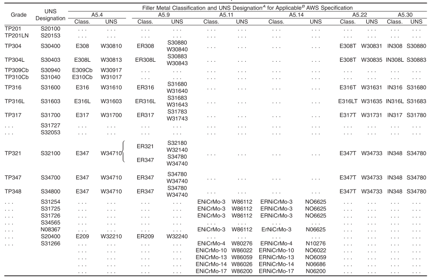
6.3 Unless otherwise specified in the purchase order, the chemical composition of the welding filler metal shall conform to the requirements of the applicable AWS specification for the corresponding grade shown in Table 2. Grades with no filler metal classification indicated shall be welded with filler metals producing deposited weld metal having a composition in accordance with the chemical composition specified in Table 1.The method of analysis for nitrogen and cerium shall be a matter of agreement between the purchaser and manufacturer.The purchaser may choose a higher-alloy filler metal when needed for corrosion resistance.
A New designation established in accordance with ASTM E527 and SAE J1086.
B The titanium content shall be not less than 5 times the carbon content and not more than 0.70 %.
C The columbium plus tantalum content shall be not less than 10 times the carbon content and not more than 1.10 %.
D The columbium plus tantalum content shall be not less than 10 times the carbon content and not more than 1.10 %. The tantalum content shall be 0.10 % maximum,CO 0.20 % maximum.
A New designation established in accordance with Practice E527 and SAE J1086, Practice for Numbering Metals and Alloys (UNS).
B Choice of American Welding Society specification depends on the welding process used.
7. Tensile Requirements
7.1 The tensile properties of the plate or sheet used in making the pipe shall conform to the requirements prescribed in Table 3. Certified mill test reports shall be submitted to the pipe manufacturer.
7.2 Atransverse tension test taken across the welded joint of the finished pipe shall meet the same minimum tensile strength requirements as the sheet or plate. The weld section on the tension specimen shall be in the same condition as the finished pipe (with or without bead as specified).
TABLE 3 Tensile Requirements
8. Mechanical Tests Required
8.1 Tension Test—One transverse tension test of the weld shall be made on each lot (Note 2) of finished pipe.
NOTE 2—The term “lot” applies to each 200 ft [60 m] or less of pipe of the same NPS and wall thickness (or schedule number) which is produced from the same heat of steel and subjected to the same finishing treatment in a continuous furnace. When final heat treatment is in a batch-type furnace, the lot shall include only that pipe which is heat treated in the same furnace charge. When no heat treatment is performed following final forming operations, the lot shall include each 200 ft [60 m] or less of pipe of the same NPS and wall thickness (or schedule number) which is produced from the same heat of steel.
8.2 Transverse Guided-Bend Weld Test—One test (two specimens) of the weld shall be made on each lot (Note 2) of finished pipe.
8.3 Pressure or Nondestructive Electric Test—Each length of pipe shall be subjected to a pressure test or a nondestructive electric test as prescribed in Section 5.
9. Permissible Variations in Wall Thickness
9.1 The minimum wall thickness at any point shall not be more than 0.018 in. [0.46 mm] under the specified wall thickness. (This tolerance is slightly more than commercial tolerances on sheet and plate to allow for possible loss of thickness caused by manufacturing operations.)
10. Permissible Variations in Dimensions
10.1 Permissible variations in dimensions shall not exceed the following at any point in each length of pipe.
10.1.1 Specified Diameter—Where the specified wall thickness is less than 0.188 in. [4.8 mm], the actual outside diameter, based on circumferential measurement, shall not vary more than 60.20 % from the specified outside diameter. Where the specified wall thickness is 0.188 in. [4.8 mm] and heavier,the actual outside diameter, based on circumferential measurement, may vary a maximum of 60.40 % from the specified outside diameter. (Outside diameter tolerances closer than shown above may be obtained by agreement between the pipe manufacturer and purchaser.)
10.1.2 Out-of-Roundness—The difference between the major and the minor outside diameter shall not be more than 1.5 % of the specified outside diameter.
10.1.3 Alignment (Camber)—Using a 10-ft [3.0-m] straightedge placed so that both ends are in contact with the pipe, the camber shall not be more than 3 ⁄ 16 in. [4.8 mm].
11. Lengths
11.1 Unless otherwise specified in the purchase order, pipe of NPS 22 or less will be furnished in random lengths of 9 to 12 ft (Note 3). For outside diameters of over NPS 22, the minimum length will be 5 ft (Note 3).
NOTE 3—This value(s) applies when the inch-pound designation of this specification is the basis of purchase. The corresponding metric value(s) shall be agreed upon between the manufacturer and the purchaser.
11.2 When specified by the purchaser, two or more lengths may be circumferentially welded together to produce longer lengths.
11.3 Circumferentially welded joints shall be of the same quality as the longitudinal joints.
12. Workmanship, Finish, and Appearance
12.1 The finished pipe shall have a workmanlike finish.
12.2 Repair of Defects by Machining or Grinding—Pipe showing moderate slivers or other surface defects may be machined or ground inside or outside to a depth which will ensure the removal of all defects providing the wall thickness is not reduced below the minimum specified in 9.1.
12.3 Repair of Defects by Welding—Defects which violate minimum wall thickness may be repaired by welding, but only with the approval of the purchaser. Areas shall be suitably prepared for welding with tightly closed defects removed by grinding. Open, clean defects, such as pits or impressions, may require no preparation. All welders, welding operators, and weld procedures shall be qualified to the ASME Boiler and Pressure Vessel Code, Section IX. Unless the purchaser specifies otherwise, pipe required to be heat treated under the provisions of 5.3 shall be heat treated or reheat treated following repair welding. Repaired lengths, where repair depth is greater than 1 ⁄ 4 of the thickness, shall be pressure tested or repressure tested after repair and heat treatment (ifany). Repair welds shall also be examined by suitable non-destructive examination techniques, including any techniques specifically required of the primary weld.
12.4 The pipe shall be free of scale and contaminating iron particles. Pickling, blasting, or surface finishing is not mandatory when pipe is bright annealed. The purchaser may request that a passivating treatment be applied.
13. Test Specimens
13.1 Transverse tension and bend test specimens may be taken from a test plate of the same material as the pipe, made by attaching a formed cylinder to the end of the pipe and welding the abutting edges as a continuation and duplication of the seam of the pipe (run-off plate). As an alternative to a formed cylinder, the run-off plate may consist of flat plates with reinforcing bars clamped to the underside to prevent distortion. The run-off plate material shall be of the same heat,preferably shear croppings from the same plate.
13.2 When heat treatment is required, test specimens shall be cut from pipe after the heat treating has been completed, or specimens removed from the pipe prior to heat treating shall be heat treated with the pipe.
14. Transverse Guided-Bend Weld Tests
14.1 Two bend test specimens shall be taken transversely across the weld. One shall be subject to a face guided-bend test and the second to a root guided-bend test. One specimen shall be bent with the inside surface of the pipe against the plunger,and the other with the outside surface against the plunger.
14.2 The bend test shall be acceptable if no cracks or other defects exceeding 1 ⁄ 8 in. [3 mm] in any direction are present in the weld metal or between the weld and the pipe metal after bending. Cracks which originate along the edges of the specimen during testing, and that are less than 1 ⁄ 4 in. [6.5 mm] measured in any direction shall not be considered.
15. Pressure Tests
15.1 Where hydrostatic test equipment is not available, the pipe may be air or gas pressure tested with an internal pressure of100 psi [700 kPa]. The weld and weld area shall be inspected with the use of soap solution or any other prepared solution which will detect the leakage of air or gas from the inside.
15.2 Instead of a pressure test, when mutually agreed upon between the purchaser and manufacturer, the entire weld area ofeach pipe, including circumferential welds, may be tested by nondestructive testing methods. These methods shall be capable of detecting both surface and subsurface defects.
16. Inspection
16.1 When specified in the purchase order, the pipe may be inspected at the manufacturer’s plant by an inspector representing the purchaser. The inspector shall have entry at all times. The manufacturer shall afford the inspector, all reasonable facilities to satisfy him that the material is being furnished in accordance with these specifications.
17. Certification
17.1 Upon request of the purchaser in the contract or order,certification in accordance with the provisions of Specification A999/A999M shall be furnished. When specified on the purchase order or when a specific type of melting has been specified on the purchase order, the type of melting used shall also be reported to the purchaser or the purchaser’s representative.
18. Product Marking
18.1 Each length of pipe manufactured in accordance with this specification shall have the following identifying marking within 12 in. [300 mm] of one end: manufacturer’s name or trade-mark, specification number, grade number of the alloy,the manufacturer’s heat number, size, and schedule number.Additional marking requirements for heat treatment are described in Supplementary Requirement S2.
18.2 Marking shall be legibly stenciled with a suitable paint or permanent marking compound, except when otherwise specified by the purchaser.
Standard Specification for
Welded Large Diameter Austenitic Steel Pipe for Corrosive or High-Temperature Service
1. Scope*
1.1 This specification covers straight seam or spiral seam electric-fusion-welded, light-wall, austenitic chromium-nickel alloy steel pipe for corrosive or high-temperature service. The sizes covered are NPS 14 to 30 with extra light (Schedule 5S) and light (Schedule 10S) wall thicknesses. Table X1.1 shows the wall thickness of Schedule 5S and 10S pipe. Pipe having other dimensions may be furnished provided such pipe complies with all other requirements of this specification.
1.2 Several grades of alloy steel are covered as indicated in Table 1.
1.3 Optional supplementary requirements are provided.These call for additional tests to be made, and when desired shall be stated in the order, together with the number of such tests required.
1.4 The values stated in either SI units or inch-pound units are to be regarded separately as standard. Within the text, the SI units are shown in brackets. The values stated in each system may not be exact equivalents; therefore, each system shall be used independently of the other. Combining values from the two systems may result in non-conformance with the standard. The inch-pound units shall apply unless the “M” designation of this specification is specified in the order.
NOTE 1—The dimensionless designator NPS (nominal pipe size) has been substituted in this standard for such traditional terms as nominal diameter, size, and nominal size.
2. Referenced Documents
2.1 ASTM Standards:
A262 Practices for Detecting Susceptibility to Intergranular Attack in Austenitic Stainless Steels
A480/A480M Specification for General Requirements for Flat-Rolled Stainless and Heat-Resisting Steel Plate,Sheet, and Strip
A999/A999M Specification for General Requirements for Alloy and Stainless Steel Pipe
E527 Practice for Numbering Metals and Alloys in the Unified Numbering System (UNS)
2.2 ASME Boiler and Pressure Vessel Code:
Section IX
2.3 AWS Standards:
A 5.22 Flux Cored Arc Welding
A 5.30 Consumable Weld Inserts for Gas Tungsten Arc Welding
A 5.4 Corrosion-Resisting Chromium and Chromium-Nickel Steel Covered Welding Electrodes
A 5.9 Corrosion-Resisting Chromium and Chromium-Nickel Steel Welding Rods and Bare Electrodes
A 5.11 Nickel and Nickel-Alloy Covered Welding Electrodes
A 5.14 Nickel and Nickel-Alloy Bare Welding Rods and Electrodes
2.4 Other Standard:
SAE J1086 Practice for Numbering Metals and Alloys (UNS) 6
3. Ordering Information
3.1 Orders for material to this specification should include the following, as required, to describe the desired material adequately:
3.1.1 Quantity (feet, centimetres, or number of lengths),
3.1.2 Name of material (straight seam or spiral seam electric-fusion-welded austenitic steel pipe),
3.1.3 Grade (Table 1),
3.1.4 Size (outside diameter and schedule number, or wall thickness).
3.1.5 Length (specific or random) (Section 11),
3.1.6 End finish (Section on Ends of Specification A999/A999M),
3.1.7 Optional requirements (5.2.1 – 5.2.3 removal of weld bead; 5.3.2, special heat treatment; 15.2, nondestructive test;10.1.1, outside diameter tolerance; 11.2, length circumferentially welded; 12.3, repair by welding and heat treatment subsequent to repair welding; 12.4, sand blasted or pickled;17.1 Certification; Supplementary Requirements S1 to S6).
3.1.8 Specification designation, and
3.1.9 Special requirements.
4. General Requirements
4.1 Material furnished to this specification shall conform to the applicable requirements of the current edition of Specification A999/A999M, unless otherwise provided herein.
5. Materials and Manufacture
5.1 If a specific type of melting is required by the purchaser it shall be stated on the order.
5.2 Welding:
5.2.1 The welds shall be made by the manual or automatic electric-welding process. For manual welding, the operator and procedure shall be qualified in accordance with the ASME Boiler and Pressure Vessel Code, Section IX. Unless otherwise specified on the purchase order, the pipe may be welded with or without filler metal when the automatic electric-welding process is used.
5.2.2 The weld surface on either side of the weld may be flush with the base plate or may have a reasonably uniform crown, not to exceed 1 ⁄ 16 in. [2 mm]. Any weld reinforcement may be removed at the manufacturer’s option or by agreement between the manufacturer and purchaser. The contour of the reinforcement should be reasonably smooth and free from irregularities. The weld metal shall be fused uniformly into the plate surface. No concavity of contour is permitted unless the resulting thickness of weld metal is equal to or greater than the minimum thickness of the adjacent base metal.
5.2.3 Weld defects, as determined by specified inspection requirements, shall be repaired by removal to sound metal and rewelding.
5.3 Heat Treatment:
5.3.1 Except as provided in 5.3.2, all pipe shall be furnished in the heat-treated condition. The heat-treatment procedure shall consist of heating the material to a minimum temperature of 1900 °F [1040 °C], except for S31254, S31266, and S30815 which shall be heat treated to 2100 °F [1150 °C] and 1920 °F [1050 °C] respectively, S31727 and S32053 which shall be heat treated in the range 1975 to 2155 °F [1080 to 1180 °C],S34565 which shall be heat treated in the range 2050 °F [1120 °C] to 2140 °F [1170 °C], and N08367, which shall be
heated to a minimum temperature of 2025 °F [1107 °C], all materials to be followed by quenching in water or rapidly cooling by other means.
5.3.2 The purchase order shall specify one of the following conditions if the heat-treated condition specified in 5.3.1 is not desired by the purchaser:
5.3.2.1 A final heat-treatment temperature under 1900 °F [1040 °C]. Each pipe supplied under this requirement shall be stenciled with the final heat-treatment temperature in degrees Fahrenheit or degrees Celsius after the suffix “HT.” Controlled structural or special service characteristics may be specified as a guide for the most suitable heat treatment.
5.3.2.2 No final heat treatment of pipe fabricated of plate,that has been solution heat treated at temperatures required by this specification. Each pipe supplied under this requirement shall be stenciled with the suffix “HT-O.”
5.3.2.3 No final heat treatment of pipe fabricated of plate,that has not been solution heat treated. Each pipe supplied under this requirement shall be stenciled with the suffix “HT-SO.”
5.4 A solution annealing temperature above 1950 °F[1065 °C] may impair the resistance to intergranular corrosion after subsequent exposure to sensitizing conditions in TP321,TP347, and TP348. When specified by the purchaser, a lower temperature stabilization or re-solution anneal shall be used subsequent to the initial high temperature solution anneal (see Supplementary Requirement S5).
6. Chemical Composition
6.1 The steel shall conform to the chemical composition in Table 1.
6.2 When specified on the purchase order, a product analysis shall be supplied from one tube or coil ofsteel per heat. The product analysis tolerance of Specification A480/A480M shall apply.
6.3 Unless otherwise specified in the purchase order, the chemical composition of the welding filler metal shall conform to the requirements of the applicable AWS specification for the corresponding grade shown in Table 2. Grades with no filler metal classification indicated shall be welded with filler metals producing deposited weld metal having a composition in accordance with the chemical composition specified in Table 1.The method of analysis for nitrogen and cerium shall be a matter of agreement between the purchaser and manufacturer.The purchaser may choose a higher-alloy filler metal when needed for corrosion resistance.
TABLE 1 Chemical Requirements
|
Grade |
UNS Designations | Composition, % | |||||||||||
|
Car- bon, max |
Man- ganese, max |
Phos- phorus, max |
Sulfur, max |
Sili- con |
Nickel | Chromium |
Molyb- denum |
Tita- nium |
Colum- bium |
Cerium | Other Elements | ||
| TP201 | S20100 | 0.15 | 5.5–7.5 | 0.060 | 0.030 | 1.00 | 3.5–5.5 | 16.0–18.0 | . . . . | . . . | . . . | . . . | N 0.25 |
| TP201LN | S20153 | 0.03 | 6.4–7.5 | 0.045 | 0.015 | 0.75 | 4.0–5.0 | 16.0–17.5 | . . . | . . . | . . . | . . . |
N 0.10–0.25, Cu 1.00 |
| TP304 | S30400 | 0.08 | 2.00 | 0.045 | 0.030 | 1.00 max | 8.0–11.0 | 18.0–20.0 | . . . | . . . | . . . | . . . | . . . |
| TP304L | S30403 | 0.035 | 2.00 | 0.045 | 0.030 | 1.00 max | 8.0–11.0 | 18.0–20.0 | . . . | . . . | . . . | . . . | . . . |
| TP309Cb | S30940 | 0.08 | 2.00 | 0.045 | 0.030 | 1.00 max | 12.0–16.0 | 22.0–24.0 | . . . | . . . | . . . | . . . |
Cb 10 × C min, 1.10 max |
| TP309S | S30908 | 0.08 | 2.00 | 0.045 | 0.030 | 1.00 max | 12.0–15.0 | 22.0–24.0 | . . . | . . . | . . . | . . . | |
| TP310Cb | S31040 | 0.08 | 2.00 | 0.045 | 0.030 | 1.00 max | 19.0–22.0 | 24.0–26.0 | . . . | . . . | . . . | . . . |
Cb 10 × C min, 1.10 max |
| TP310S | S31008 | 0.08 | 2.00 | 0.045 | 0.030 | 1.00 max | 19.0–22.0 | 24.0–26.0 | . . . | . . . | . . . | . . . | |
| TP316 | S31600 | 0.08 | 2.00 | 0.045 | 0.030 | 1.00 max | 10.0–14.0 | 16.0–18.0 | 2.00–3.00 | . . . | . . . | . . . | |
| TP316L | S31603 | 0.035 | 2.00 | 0.045 | 0.030 | 1.00 max | 10.0–14.0 | 16.0–18.0 | 2.00–3.00 | . . . | . . . | . . . | |
| TP317 | S31700 | 0.08 | 2.00 | 0.045 | 0.030 | 1.00 max | 11.0–15.0 | 18.0–20.0 | 3.0–4.0 | . . . | . . . | . . . | |
| . . . | S31727 | 0.030 | 1.00 | 0.030 | 0.030 | 1.00 max | 14.5–16.5 | 17.5–19.0 | 3.8–4.5 | . . . | . . . | . . . |
N 0.15–0.21 Cu 2.8–4.0 |
| . . . | S32053 | 0.030 | 1.00 | 0.030 | 0.010 | 1.00 max | 24.0–26.0 | 22.0–24.0 | 5.0–6.0 | . . . | . . . | . . . | N 0.17–0.22 |
| TP321 | S32100 | 0.08 | 2.00 | 0.045 | 0.030 | 1.00 max | 9.00–12.0 | 17.0–20.0 | . . . | B | . . . | . . . | |
| TP347 | S34700 | 0.08 | 2.00 | 0.045 | 0.030 | 1.00 max | 9.00–12.0 | 17.0–19.0 | . . . | . . . | C | . . . | |
| TP348 | S34800 | 0.08 | 2.00 | 0.045 | 0.030 | 1.00 max | 9.00–12.0 | 17.0–19.0 | . . . | . . . | D | . . . | |
| . . . | S31254 | 0.020 | 1.00 | 0.030 | 0.010 | 0.80 max | 17.5–18.5 | 19.5–19.5 | 6.0–6.5 | . . . | . . . | . . . |
Cu 0.50–1.00 N 0.18–0.25 |
| . . . | S30815 | 0.05–0.10 | 0.80 | 0.040 | 0.030 | 1.40–2.00 | 10.0–12.0 | 20.0–22.0 | . . . | . . . | . . . | 0.03–0.08 | N 0.14–0.20 |
| . . . | S31725 | 0.030 | 2.00 | 0.045 | 0.030 | 1.00 max | 13.5–17.5 | 18.0–20.0 | 4.0–5.0 | . . . | . . . | . . . | N 0.020 max |
| . . . | S31726 | 0.030 | 2.00 | 0.045 | 0.030 | 1.00 max | 14.5–17.5 | 17.0–20.0 | 4.0–5.0 | . . . | . . . | . . . | N 0.10–0.20 |
| . . . | S34565 | 0.030 | 5.0–7.0 | 0.030 | 0.010 | 1.00 max | 16.0–18.0 | 23.0–25.0 | 4.0–5.0 | . . . |
0.10 max |
. . . | N 0.40–0.60 |
| . . . | N08367 | 0.030 | 2.00 | 0.040 | 0.030 | 1.00 max | 23.5–25.5 | 20.0–22.0 | 6.0–7.0 | . . . | . . . | . . . |
Cu 0.75 max Ni 0.18–0.25 |
| . . . | S20400 | 0.030 | 7.0–9.0 | 0.45 | 0.030 | 1.00 max | 1.50–3.00 | 15.0–17.0 | . . . | . . . | . . . | . . . | N 0.15–0.30 |
| . . . | S31266 | 0.030 | 2.00–4.00 | 0.035 | 0.020 | 1.00 max | 21.0–24.0 | 23.0–25.0 | 5.2–6.2 | . . . | . . . | . . . |
Cu 1.00–2.50 W 1.50–2.50 N 0.35–0.60 |
A New designation established in accordance with ASTM E527 and SAE J1086.
B The titanium content shall be not less than 5 times the carbon content and not more than 0.70 %.
C The columbium plus tantalum content shall be not less than 10 times the carbon content and not more than 1.10 %.
D The columbium plus tantalum content shall be not less than 10 times the carbon content and not more than 1.10 %. The tantalum content shall be 0.10 % maximum,CO 0.20 % maximum.
TABLE 2 Filler Metal Specifications
A New designation established in accordance with Practice E527 and SAE J1086, Practice for Numbering Metals and Alloys (UNS).
B Choice of American Welding Society specification depends on the welding process used.
7. Tensile Requirements
7.1 The tensile properties of the plate or sheet used in making the pipe shall conform to the requirements prescribed in Table 3. Certified mill test reports shall be submitted to the pipe manufacturer.
7.2 Atransverse tension test taken across the welded joint of the finished pipe shall meet the same minimum tensile strength requirements as the sheet or plate. The weld section on the tension specimen shall be in the same condition as the finished pipe (with or without bead as specified).
TABLE 3 Tensile Requirements
| Grade | UNS Designation | Tensile Strength,min, ksi [MPa] | Yield Strength,min, ksi [MPa] |
| TP201 | S20100 | 75 [515] | 38 [260] |
| TP201LN | S20153 | 95 [655] | 45 [310] |
| TP304 | S30400 | 75 [515] | 30 [205] |
| TP304L | S30403 | 70 [485] | 25 [170] |
| TP309Cb | S30940 | 75 [515] | 30 [205] |
| TP309S | S30908 | 75 [515] | 30 [205] |
| TP310Cb | S31040 | 75 [515] | 30 [205] |
| TP310S | S31008 | 75 [515] | 30 [205] |
| TP316 | S31600 | 75 [515] | 30 [205] |
| TP316L | S31603 | 70 [485] | 25 [170] |
| TP317 | S31700 | 75 [515] | 30 [205] |
| . . . | S31727 | 80 [550] | 36 [245] |
| . . . | S32053 | 93 [640] | 43 [295] |
| TP321 | S32100 | 75 [515] | 30 [205] |
| TP347 | S34700 | 75 [515] | 30 [205] |
| TP348 | S34800 | 75 [515] | 30 [205] |
| . . . | S31254 | 94 [650] | 44 [300] |
| . . . | S30815 | 87 [600] | 45 [310] |
| . . . | S31725 | 75 [515] | 30 [205] |
| . . . | S31726 | 80 [550] | 35 [240] |
| . . . | S34565 | 115 [795] | 60 [415] |
| . . . | S20400 | 95 [655] | 48 [330] |
| . . . | N08367 t ≤ 0.187 | 100 [690] | 45 [310] |
| N08367 t > 0.187 | 95 [655] | 45 [310] | |
| . . . | S31266 | 109 [750] | 61 [420] |
8. Mechanical Tests Required
8.1 Tension Test—One transverse tension test of the weld shall be made on each lot (Note 2) of finished pipe.
NOTE 2—The term “lot” applies to each 200 ft [60 m] or less of pipe of the same NPS and wall thickness (or schedule number) which is produced from the same heat of steel and subjected to the same finishing treatment in a continuous furnace. When final heat treatment is in a batch-type furnace, the lot shall include only that pipe which is heat treated in the same furnace charge. When no heat treatment is performed following final forming operations, the lot shall include each 200 ft [60 m] or less of pipe of the same NPS and wall thickness (or schedule number) which is produced from the same heat of steel.
8.2 Transverse Guided-Bend Weld Test—One test (two specimens) of the weld shall be made on each lot (Note 2) of finished pipe.
8.3 Pressure or Nondestructive Electric Test—Each length of pipe shall be subjected to a pressure test or a nondestructive electric test as prescribed in Section 5.
9. Permissible Variations in Wall Thickness
9.1 The minimum wall thickness at any point shall not be more than 0.018 in. [0.46 mm] under the specified wall thickness. (This tolerance is slightly more than commercial tolerances on sheet and plate to allow for possible loss of thickness caused by manufacturing operations.)
10. Permissible Variations in Dimensions
10.1 Permissible variations in dimensions shall not exceed the following at any point in each length of pipe.
10.1.1 Specified Diameter—Where the specified wall thickness is less than 0.188 in. [4.8 mm], the actual outside diameter, based on circumferential measurement, shall not vary more than 60.20 % from the specified outside diameter. Where the specified wall thickness is 0.188 in. [4.8 mm] and heavier,the actual outside diameter, based on circumferential measurement, may vary a maximum of 60.40 % from the specified outside diameter. (Outside diameter tolerances closer than shown above may be obtained by agreement between the pipe manufacturer and purchaser.)
10.1.2 Out-of-Roundness—The difference between the major and the minor outside diameter shall not be more than 1.5 % of the specified outside diameter.
10.1.3 Alignment (Camber)—Using a 10-ft [3.0-m] straightedge placed so that both ends are in contact with the pipe, the camber shall not be more than 3 ⁄ 16 in. [4.8 mm].
11. Lengths
11.1 Unless otherwise specified in the purchase order, pipe of NPS 22 or less will be furnished in random lengths of 9 to 12 ft (Note 3). For outside diameters of over NPS 22, the minimum length will be 5 ft (Note 3).
NOTE 3—This value(s) applies when the inch-pound designation of this specification is the basis of purchase. The corresponding metric value(s) shall be agreed upon between the manufacturer and the purchaser.
11.2 When specified by the purchaser, two or more lengths may be circumferentially welded together to produce longer lengths.
11.3 Circumferentially welded joints shall be of the same quality as the longitudinal joints.
12. Workmanship, Finish, and Appearance
12.1 The finished pipe shall have a workmanlike finish.
12.2 Repair of Defects by Machining or Grinding—Pipe showing moderate slivers or other surface defects may be machined or ground inside or outside to a depth which will ensure the removal of all defects providing the wall thickness is not reduced below the minimum specified in 9.1.
12.3 Repair of Defects by Welding—Defects which violate minimum wall thickness may be repaired by welding, but only with the approval of the purchaser. Areas shall be suitably prepared for welding with tightly closed defects removed by grinding. Open, clean defects, such as pits or impressions, may require no preparation. All welders, welding operators, and weld procedures shall be qualified to the ASME Boiler and Pressure Vessel Code, Section IX. Unless the purchaser specifies otherwise, pipe required to be heat treated under the provisions of 5.3 shall be heat treated or reheat treated following repair welding. Repaired lengths, where repair depth is greater than 1 ⁄ 4 of the thickness, shall be pressure tested or repressure tested after repair and heat treatment (ifany). Repair welds shall also be examined by suitable non-destructive examination techniques, including any techniques specifically required of the primary weld.
12.4 The pipe shall be free of scale and contaminating iron particles. Pickling, blasting, or surface finishing is not mandatory when pipe is bright annealed. The purchaser may request that a passivating treatment be applied.
13. Test Specimens
13.1 Transverse tension and bend test specimens may be taken from a test plate of the same material as the pipe, made by attaching a formed cylinder to the end of the pipe and welding the abutting edges as a continuation and duplication of the seam of the pipe (run-off plate). As an alternative to a formed cylinder, the run-off plate may consist of flat plates with reinforcing bars clamped to the underside to prevent distortion. The run-off plate material shall be of the same heat,preferably shear croppings from the same plate.
13.2 When heat treatment is required, test specimens shall be cut from pipe after the heat treating has been completed, or specimens removed from the pipe prior to heat treating shall be heat treated with the pipe.
14. Transverse Guided-Bend Weld Tests
14.1 Two bend test specimens shall be taken transversely across the weld. One shall be subject to a face guided-bend test and the second to a root guided-bend test. One specimen shall be bent with the inside surface of the pipe against the plunger,and the other with the outside surface against the plunger.
14.2 The bend test shall be acceptable if no cracks or other defects exceeding 1 ⁄ 8 in. [3 mm] in any direction are present in the weld metal or between the weld and the pipe metal after bending. Cracks which originate along the edges of the specimen during testing, and that are less than 1 ⁄ 4 in. [6.5 mm] measured in any direction shall not be considered.
15. Pressure Tests
15.1 Where hydrostatic test equipment is not available, the pipe may be air or gas pressure tested with an internal pressure of100 psi [700 kPa]. The weld and weld area shall be inspected with the use of soap solution or any other prepared solution which will detect the leakage of air or gas from the inside.
15.2 Instead of a pressure test, when mutually agreed upon between the purchaser and manufacturer, the entire weld area ofeach pipe, including circumferential welds, may be tested by nondestructive testing methods. These methods shall be capable of detecting both surface and subsurface defects.
16. Inspection
16.1 When specified in the purchase order, the pipe may be inspected at the manufacturer’s plant by an inspector representing the purchaser. The inspector shall have entry at all times. The manufacturer shall afford the inspector, all reasonable facilities to satisfy him that the material is being furnished in accordance with these specifications.
17. Certification
17.1 Upon request of the purchaser in the contract or order,certification in accordance with the provisions of Specification A999/A999M shall be furnished. When specified on the purchase order or when a specific type of melting has been specified on the purchase order, the type of melting used shall also be reported to the purchaser or the purchaser’s representative.
18. Product Marking
18.1 Each length of pipe manufactured in accordance with this specification shall have the following identifying marking within 12 in. [300 mm] of one end: manufacturer’s name or trade-mark, specification number, grade number of the alloy,the manufacturer’s heat number, size, and schedule number.Additional marking requirements for heat treatment are described in Supplementary Requirement S2.
18.2 Marking shall be legibly stenciled with a suitable paint or permanent marking compound, except when otherwise specified by the purchaser.