ASTM A381 Metal-Arc-Welded Steel Pipe
ASTM A381
Standard Specification for Metal-Arc-Welded Steel Pipe for Use With High-Pressure Transmission Systems
1. Scope
1.1 This specification covers straight seam, double-submerged-arc-welded steel pipe (Note 1) suitable for high-pressure service, 16 in. (406 mm) and larger in outside diameter, with wall thicknesses from
5 ⁄ 16 to 1 1 ⁄ 2 in. (7.9 to 38mm). The pipe is intended for fabrication of fittings and accessories for compressor or pump-station piping. Pipe ordered to this specification shall be suitable for bending,flanging (vastoning), corrugating, and similar operations.
NOTE 1—A comprehensive listing of standardized pipe dimensions is contained in ANSI B36.10.
NOTE 2—The term “double welded” is commonly used in the gas and oil transmission industry, for which this pipe is primarily intended, to indicate welding with at least two weld passes, of which one is on the outside of the pipe and one on the inside.
For some sizes of the pipe covered by this specification, it becomes expedient to use manual welding, in which case the provisions of Note 3 shall be followed.
1.2 Nine classes of pipe, based on minimum yield point requirements, are covered as indicated in Table 1.
1.3 The values stated in inch-pound units are to be regarded as the standard. The metric equivalents of inch-pound units may be approximate.
1.4 The following hazard caveat applies to the test methods portion, Sections 9 and 10, only. This standard does not purport to address all of the safety problems, if any, associated with its use. It is the responsibility of the user of this standard to establish appropriate safety and health practices and determine the applicability of regulatory limitations prior to use.
2. Referenced Documents
2.1 ASTM Standards:
A 370 Test Methods and Definitions for Mechanical Testing of Steel Products
A 530/A 530M Specification for General Requirements for Specialized Carbon and Alloy Steel Pipe
E 30 Test Methods for Chemical Analysis of Steel, Cast Iron, Open-Hearth Iron, and Wrought Iron
2.2 ASME Boiler and Pressure Vessel Code:
Section VIII Pressure Vessels
Section IX Welding Qualifications
2.3 ANSI Standard:
ANSI B36.10 Welded and Seamless Wrought Steel Pipe
3. Ordering Information
3.1 Orders for material to this specification should include the following, as required, to describe the desired material adequately:
3.1.1 Quantity (feet, centimetres, or number of lengths),
3.1.2 Name of material (metal-arc welded pipe),
3.1.3 Class (Table 1),
3.1.4 Material (carbon or alloy steel, Section 5),
3.1.5 Size (outside diameter and wall thickness),
3.1.6 Length (specific or random) (Section 13),
3.1.7 Ends (Section 14),
3.1.8 Heat treatment (stress-relieved or normalized) (see5.6),
3.1.9 Optional requirements (see 5.2 (Note 3), Sections 11 and 15),
3.1.10 Specification number, and
3.1.11 Special requirements or exceptions to this specification.
4. General Requirements
4.1 Material furnished to this specification shall conform to the applicable requirements of the current edition of Specification A 530/A 530M, unless otherwise provided herein.
5. Materials and Manufacture
5.1 The steel plate used in the manufacture of the pipe shall be of suitable welding quality carbon steel, or of suitable welding quality high-strength, low-alloy steel, as agreed upon between the manufacturer and purchaser.
5.2 The longitudinal edges of the plate shall be shaped to give the most satisfactory results by the particular welding process employed. The plate shall be properly formed and may be tacked preparatory to welding. The weld (except tack welds) shall be made preferably by the automatic submerged-arc-welding process (Note 3) and shall be of reasonably uniform width and height for the entire length of the pipe.
NOTE 3—By agreement between the manufacturer and the purchaser, manual welding by qualified welders using a qualified procedure may be used as an equal alternate to this specification.
5.3 Both longitudinal and circumferential (if any) joints shall be double welded, full penetration welds being made in accordance with procedures and by welders or welding operators qualified in accordance with the ASME Boiler and Pressure Vessel Code, Section IX.
5.4 The contour of the reinforcement shall be smooth, with no valley or groove along the edge or in the center of the weld,and the deposited metal shall be fused smoothly and uniformly into the plate surface. The finish of the welded joint shall be reasonably smooth and free from irregularities, grooves, or depressions.
5.5 All pipe, after welding, shall be heat treated at a temperature of 1100°F (593°C) or higher.
5.6 When specified in the purchase order, all pipe after welding shall be heated at 1650 to 1750°F (899 to 954°C) and air cooled.
6. Chemical Composition
6.1 The carbon steels shall conform to the requirements as to chemical composition specified in Table 2.
6.2 The high-strength low-alloy steels shall be of specified chemical composition in order to ensure weldability and specified minimum tensile properties including elongation.
6.3 Mill test reports, as provided by the manufacturer of the plate, shall be furnished representing the chemical analysis of each heat of steel from which the plates are rolled. This chemical analysis shall conform to the requirements of 5.1, 6.1,or 6.2.
6.4 For referee purposes, Test Methods E 30 shall be used.
7. Tensile Requirements
7.1 The tensile properties of transverse body-test specimens taken from the finished pipe shall conform to the requirements prescribed in Table 1. The tensile strength of the transverse weld-test specimens shall conform to that specified in Table 1.
7.2 Transverse body-test specimens shall be taken approxi-mately opposite the weld; transverse weld-test specimens shall be taken with the weld at the center of the specimen. For pipe wall thicknesses up to 3 ⁄ 4 in. (19 mm), incl, all transverse test specimens shall be approximately 1 1 ⁄ 2 -in. (38-mm) wide in the gage length and shall represent the full wall thickness of the pipe from which the specimen was cut (see Fig. 23, Test Methods and Definitions A 370). For pipe with wall thicknesses over 3 ⁄ 4 in. (19 mm), the standard 0.505-in. (12.83 mm) round tension test specimen with 2-in. (50.8 mm) gage length shall be used (see Fig. 5, Test Methods and Definitions A 370).
7.3 If the tension test specimen from any lot of pipe fails to conform to the requirements for the particular grade of pipe ordered, the manufacturer may elect to make retests on two additional lengths of pipe from the same lot, each of which shall conform to the requirements prescribed in Table 2. If one or both of the retests fail to conform to the requirements, the manufacturer may elect to test each of the remaining lengths of pipe in the lot. Retests are required only for the particular test with which the pipe specimen did not comply originally.
7.4 All test specimens which are flattened cold may be reheat treated before machining.
8. Transverse Guided-Bend Tests Weld
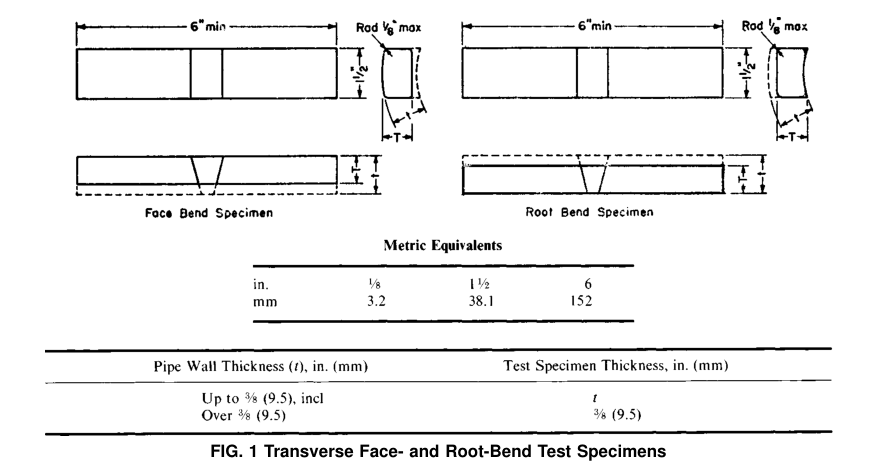
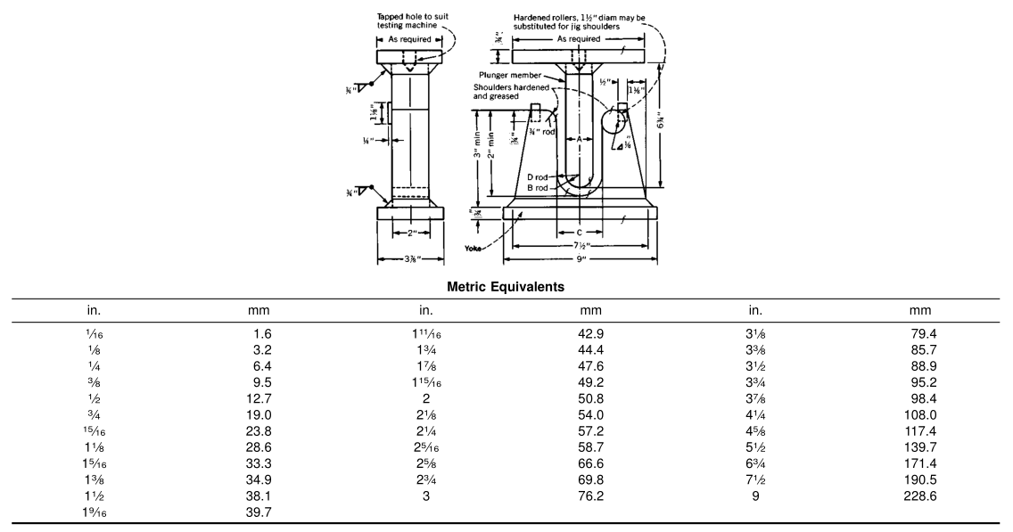
8.1 Transverse weld test specimens shall be subject to face and root guided-bend tests. The specimens shall be approxi-mately 1 1 ⁄ 2 in. (38.1 mm) wide, at least 6 in. (152 mm) in length with the weld at the center, and shall be machined in accordance with Fig. 1. One specimen shall be bent with the inside surface of the pipe against the plunger, and the other specimen with the outside surface against the plunger. The dimensions of the plunger for the bending jig shall be in accordance with Fig. 2 and the other dimensions shall be substantially as shown in Fig. 2.
8.2 The bend test shall be acceptable if no cracks or other defects exceeding 1 ⁄ 8 in. (3.17 mm) in any direction are present in the weld metal or between the weld and pipe metal after bending. Cracks which originate along the edges of the specimen during testing, and that are less than 1 ⁄ 4 in. (6.35mm), measured in any direction, shall not be considered.
9. Hydrostatic Test
9.1 Each length of pipe with wall thickness of 1 ⁄ 2in. (12.7mm) and less shall be tested to a hydrostatic pressure which will produce in the pipe wall a stress of not less than 85 % of the minimum specified yield point. This pressure shall be determined by the following equation:
P= 2St/D
where:
P= hydrostatic test pressure, psi,
S = 85 % of the specified minimum yield strength of Table 1,
t = specified wall thickness, in., and
D = specified outside diameter, in.
9.2 Each length of pipe with a wall thickness over 1 ⁄ 2 in.(12.7 mm) shall be tested to a hydrostatic pressure calculated as in 9.1 except that the stress S shall be 70 % of the specified yield point, and that a 3000-psi (20.6-MPa) maximum test pressure shall apply.
9.3 When specified in the order, pipe may be furnished without hydrostatic testing, and each length so furnished shall include with the mandatory marking the letters “NH”.
9.4 When certification is required by the purchaser and the hydrostatic test has been omitted, the certification shall clearly state “Not Hydrostatically Tested”, and the specification number and class, as shown on the certification, shall be followed by the letters “NH”.
10. Mechanical Tests Required
10.1 Transverse Body Tension Test—One test shall be made on one length of pipe from each lot of 100 lengths or less, of each size and heat, to determine the yield strength, tensile strength, and percent of elongation in 2 in. (50.8 mm).
10.2 Transverse Weld Tension Test—One test shall be made on one length of pipe from each lot of 100 lengths or less, of each size, for tensile strength only.
10.3 Transverse Guided-Bend Weld Test:
10.3.1 Two weld bend test specimens as described in 8.1 shall be cut from a length of pipe from each lot of 50 lengths or less, of each size. Bend test specimens shall be cut from pipe ends which have not been repaired.
10.3.2 If either test fails to conform to specified requirements, the manufacturer may elect to make retests on two additional lengths of pipe from the same lot, each of which shall conform to the requirements specified in 8.2. If any of the retests fail to conform to the requirements, the manufacturer may elect to test each of the remaining lengths of pipe in the lot.
10.4 Hydrostatic Test—Each length of pipe shall be subjected to the hydrostatic test.
11. Radiographic Examination
11.1 The manufacturer shall employ radiography as a production control on the welding employed in the manufacture of pipe to this specification. At least 5 % of the total linear footage of welding shall be subjected to radiographic examination to ensure that the welding equipment is consistently producing the required quality. The selection of the sections to be so examined shall be at the discretion of the manufacturer’s inspector. The purchaser’s inspector shall have access to the radiographic films and records of current production.
11.2 When so specified on the purchase order, all welding performed under these specifications shall be fully radiographed. The procedures and requirements shall conform to Paragraph UW-51 of the ASME Boiler and Pressure Vessel Code, Section VIII (latest edition).
12. Permissible Variations in Dimensions
12.1 Permissible variations in dimensions shall not exceed the following:
12.1.1 Outside Diameter—60.5 % of the specified outside diameter for the outside diameter based on circumferential measurement, except that in sizes 24 in. (610 mm) and smaller this tolerance shall be 6 1 ⁄ 8 in. (3.2 mm).
12.1.2 Out-of-Roundness—1 %, that is, the difference between the major and minor outside diameter.
12.1.3 Thickness—The minimum wall thickness shall not be more than 0.01 in. (0.25 mm) under the specified thickness. Localized (isolated and noncontinuous) reductions in wall thickness caused by noninjurious surface defects may be permitted up to a depth not exceeding 6 1 ⁄ 2 % the specified pipe wall thickness.
13. Lengths
13.1 Unless otherwise specified, pipe shall be furnished in approximately 20-ft (6.1-m) lengths.
13.2 Where longer lengths are required, circumferentially welded joints shall be permitted.
13.3 Shorter lengths, when required, shall be specified in the order.
14. Ends
14.1 Pipe ends shall be furnished beveled as specified in the order. The width of the end shall be 1 ⁄ 16 in. (1.6 mm) with a tolerance of 6 1 ⁄ 32 in. (0.8 mm).
14.2 The end of the pipe shall not be out of square more than 1 ⁄ 16 in. (1.6 mm).
15. Workmanship, Finish, and Appearance
15.1 The finished pipe shall be free of injurious defects and shall have a workmanlike finish.
15.2 Repair of Plate Defects by Machining or Grinding—Pipe showing moderate slivers may be machined or ground inside or outside to a depth which shall ensure the removal of all included scale and slivers, providing the wall thickness is not reduced below the specified minimum wall thickness.
15.3 Repair of Plate Defects by Welding—Repair of plate defects by welding shall be permitted. Welding of injurious defects shall not be permitted when the depth of defect exceeds 33 1 ⁄ 3 % of the specified pipe wall thickness or the length of repair exceeds 25 % of the specified diameter of the pipe.Defects must be thoroughly removed and the welding performed by a welder qualified in accordance with the requirements of Section IX of the ASME Boiler and Pressure Vessel Code. Such repair welding shall be ground or machined flush with the surface of the pipe. All repair welding shall be done before final heat treatment.
16. Coating
16.1 Unless otherwise specified in the purchase order, the pipe shall be furnished uncoated.
17. Inspection
17.1 The inspector representing the purchaser shall have entry, at all times while work on the contract of the purchaser is being performed, to all parts of the manufacturer’s works that concern the manufacture of the material ordered. All reasonable facilities shall be afforded the inspector, to satisfy him that the material is being furnished in accordance with this specification. All tests called for by this specification and inspection shall be made at the place of manufacture prior to shipment unless otherwise specified, and shall be so conducted as not to interfere unnecessarily with the operation of the works.
18. Product Marking
18.1 In addition to the marking prescribed in Specification A 530/A 530M, the marking shall include the hydrostatic test pressure. Marking shall be by stenciling along the welded seam.
18.2 Bar Coding—In addition to the requirements in 18.1,bar coding is acceptable as a supplementary identification method. Bar coding should be consistent with the Automotive Industry Action Group (AIAG) standard prepared by the Primary Metals Subcommittee of the AIAG Bar Code Project Team.
19. Keywords
19.1 arc welded steel pipe; steel pipe
Standard Specification for Metal-Arc-Welded Steel Pipe for Use With High-Pressure Transmission Systems
1. Scope
1.1 This specification covers straight seam, double-submerged-arc-welded steel pipe (Note 1) suitable for high-pressure service, 16 in. (406 mm) and larger in outside diameter, with wall thicknesses from
5 ⁄ 16 to 1 1 ⁄ 2 in. (7.9 to 38mm). The pipe is intended for fabrication of fittings and accessories for compressor or pump-station piping. Pipe ordered to this specification shall be suitable for bending,flanging (vastoning), corrugating, and similar operations.
NOTE 1—A comprehensive listing of standardized pipe dimensions is contained in ANSI B36.10.
NOTE 2—The term “double welded” is commonly used in the gas and oil transmission industry, for which this pipe is primarily intended, to indicate welding with at least two weld passes, of which one is on the outside of the pipe and one on the inside.
For some sizes of the pipe covered by this specification, it becomes expedient to use manual welding, in which case the provisions of Note 3 shall be followed.
1.2 Nine classes of pipe, based on minimum yield point requirements, are covered as indicated in Table 1.
1.3 The values stated in inch-pound units are to be regarded as the standard. The metric equivalents of inch-pound units may be approximate.
1.4 The following hazard caveat applies to the test methods portion, Sections 9 and 10, only. This standard does not purport to address all of the safety problems, if any, associated with its use. It is the responsibility of the user of this standard to establish appropriate safety and health practices and determine the applicability of regulatory limitations prior to use.
2. Referenced Documents
2.1 ASTM Standards:
A 370 Test Methods and Definitions for Mechanical Testing of Steel Products
A 530/A 530M Specification for General Requirements for Specialized Carbon and Alloy Steel Pipe
E 30 Test Methods for Chemical Analysis of Steel, Cast Iron, Open-Hearth Iron, and Wrought Iron
2.2 ASME Boiler and Pressure Vessel Code:
Section VIII Pressure Vessels
Section IX Welding Qualifications
2.3 ANSI Standard:
ANSI B36.10 Welded and Seamless Wrought Steel Pipe
3. Ordering Information
3.1 Orders for material to this specification should include the following, as required, to describe the desired material adequately:
3.1.1 Quantity (feet, centimetres, or number of lengths),
3.1.2 Name of material (metal-arc welded pipe),
3.1.3 Class (Table 1),
3.1.4 Material (carbon or alloy steel, Section 5),
3.1.5 Size (outside diameter and wall thickness),
3.1.6 Length (specific or random) (Section 13),
3.1.7 Ends (Section 14),
3.1.8 Heat treatment (stress-relieved or normalized) (see5.6),
3.1.9 Optional requirements (see 5.2 (Note 3), Sections 11 and 15),
3.1.10 Specification number, and
3.1.11 Special requirements or exceptions to this specification.
TABLE 1 Tensile Requirements
| Class |
Yield Strength, min, psi (MPa) |
Tensile Strength, min, psi (MPa) |
Elongation in 2 in. (50.8 mm),min, % |
| Y 35 | 35 000 (240) | 60 000 (415) | 26 |
| Y 42 | 42 000 (290) | 60 000 (415) | 25 |
| Y 46 | 46 000 (316) | 63 000 (435) | 23 |
| Y 48 | 48 000 (330) | 62 000 (430) | 21 |
| Y 50 | 50 000 (345) | 64 000 (440) | 21 |
| Y 52 | 52 000 (360) | 66 000 (455) | 20 |
| Y 56 | 56 000 (385) | 71 000 (490) | 20 |
| Y 60 | 60 000 (415) | 75 000 (515) | 20 |
| Y 65 | 65 000 (450) | 77 000 (535) | 20 |
4. General Requirements
4.1 Material furnished to this specification shall conform to the applicable requirements of the current edition of Specification A 530/A 530M, unless otherwise provided herein.
5. Materials and Manufacture
5.1 The steel plate used in the manufacture of the pipe shall be of suitable welding quality carbon steel, or of suitable welding quality high-strength, low-alloy steel, as agreed upon between the manufacturer and purchaser.
5.2 The longitudinal edges of the plate shall be shaped to give the most satisfactory results by the particular welding process employed. The plate shall be properly formed and may be tacked preparatory to welding. The weld (except tack welds) shall be made preferably by the automatic submerged-arc-welding process (Note 3) and shall be of reasonably uniform width and height for the entire length of the pipe.
NOTE 3—By agreement between the manufacturer and the purchaser, manual welding by qualified welders using a qualified procedure may be used as an equal alternate to this specification.
5.3 Both longitudinal and circumferential (if any) joints shall be double welded, full penetration welds being made in accordance with procedures and by welders or welding operators qualified in accordance with the ASME Boiler and Pressure Vessel Code, Section IX.
5.4 The contour of the reinforcement shall be smooth, with no valley or groove along the edge or in the center of the weld,and the deposited metal shall be fused smoothly and uniformly into the plate surface. The finish of the welded joint shall be reasonably smooth and free from irregularities, grooves, or depressions.
5.5 All pipe, after welding, shall be heat treated at a temperature of 1100°F (593°C) or higher.
5.6 When specified in the purchase order, all pipe after welding shall be heated at 1650 to 1750°F (899 to 954°C) and air cooled.
6. Chemical Composition
6.1 The carbon steels shall conform to the requirements as to chemical composition specified in Table 2.
6.2 The high-strength low-alloy steels shall be of specified chemical composition in order to ensure weldability and specified minimum tensile properties including elongation.
6.3 Mill test reports, as provided by the manufacturer of the plate, shall be furnished representing the chemical analysis of each heat of steel from which the plates are rolled. This chemical analysis shall conform to the requirements of 5.1, 6.1,or 6.2.
6.4 For referee purposes, Test Methods E 30 shall be used.
TABLE 2 Chemical Requirements for Carbon Steels on Product Analysis
| Element | Composition, %, max | |
| Ladle | Check | |
| Carbon | 0.26 | 0.30 |
| Manganese | 1.40 | 1.50 |
| Phosphorus | 0.025 | 0.030 |
| Sulfur | 0.025 | 0.025 |
7. Tensile Requirements
7.1 The tensile properties of transverse body-test specimens taken from the finished pipe shall conform to the requirements prescribed in Table 1. The tensile strength of the transverse weld-test specimens shall conform to that specified in Table 1.
7.2 Transverse body-test specimens shall be taken approxi-mately opposite the weld; transverse weld-test specimens shall be taken with the weld at the center of the specimen. For pipe wall thicknesses up to 3 ⁄ 4 in. (19 mm), incl, all transverse test specimens shall be approximately 1 1 ⁄ 2 -in. (38-mm) wide in the gage length and shall represent the full wall thickness of the pipe from which the specimen was cut (see Fig. 23, Test Methods and Definitions A 370). For pipe with wall thicknesses over 3 ⁄ 4 in. (19 mm), the standard 0.505-in. (12.83 mm) round tension test specimen with 2-in. (50.8 mm) gage length shall be used (see Fig. 5, Test Methods and Definitions A 370).
7.3 If the tension test specimen from any lot of pipe fails to conform to the requirements for the particular grade of pipe ordered, the manufacturer may elect to make retests on two additional lengths of pipe from the same lot, each of which shall conform to the requirements prescribed in Table 2. If one or both of the retests fail to conform to the requirements, the manufacturer may elect to test each of the remaining lengths of pipe in the lot. Retests are required only for the particular test with which the pipe specimen did not comply originally.
7.4 All test specimens which are flattened cold may be reheat treated before machining.
8. Transverse Guided-Bend Tests Weld
8.1 Transverse weld test specimens shall be subject to face and root guided-bend tests. The specimens shall be approxi-mately 1 1 ⁄ 2 in. (38.1 mm) wide, at least 6 in. (152 mm) in length with the weld at the center, and shall be machined in accordance with Fig. 1. One specimen shall be bent with the inside surface of the pipe against the plunger, and the other specimen with the outside surface against the plunger. The dimensions of the plunger for the bending jig shall be in accordance with Fig. 2 and the other dimensions shall be substantially as shown in Fig. 2.
8.2 The bend test shall be acceptable if no cracks or other defects exceeding 1 ⁄ 8 in. (3.17 mm) in any direction are present in the weld metal or between the weld and pipe metal after bending. Cracks which originate along the edges of the specimen during testing, and that are less than 1 ⁄ 4 in. (6.35mm), measured in any direction, shall not be considered.
9. Hydrostatic Test
9.1 Each length of pipe with wall thickness of 1 ⁄ 2in. (12.7mm) and less shall be tested to a hydrostatic pressure which will produce in the pipe wall a stress of not less than 85 % of the minimum specified yield point. This pressure shall be determined by the following equation:
P= 2St/D
where:
P= hydrostatic test pressure, psi,
S = 85 % of the specified minimum yield strength of Table 1,
t = specified wall thickness, in., and
D = specified outside diameter, in.
9.2 Each length of pipe with a wall thickness over 1 ⁄ 2 in.(12.7 mm) shall be tested to a hydrostatic pressure calculated as in 9.1 except that the stress S shall be 70 % of the specified yield point, and that a 3000-psi (20.6-MPa) maximum test pressure shall apply.
9.3 When specified in the order, pipe may be furnished without hydrostatic testing, and each length so furnished shall include with the mandatory marking the letters “NH”.
9.4 When certification is required by the purchaser and the hydrostatic test has been omitted, the certification shall clearly state “Not Hydrostatically Tested”, and the specification number and class, as shown on the certification, shall be followed by the letters “NH”.
10. Mechanical Tests Required
10.1 Transverse Body Tension Test—One test shall be made on one length of pipe from each lot of 100 lengths or less, of each size and heat, to determine the yield strength, tensile strength, and percent of elongation in 2 in. (50.8 mm).
10.2 Transverse Weld Tension Test—One test shall be made on one length of pipe from each lot of 100 lengths or less, of each size, for tensile strength only.
10.3 Transverse Guided-Bend Weld Test:
10.3.1 Two weld bend test specimens as described in 8.1 shall be cut from a length of pipe from each lot of 50 lengths or less, of each size. Bend test specimens shall be cut from pipe ends which have not been repaired.
10.3.2 If either test fails to conform to specified requirements, the manufacturer may elect to make retests on two additional lengths of pipe from the same lot, each of which shall conform to the requirements specified in 8.2. If any of the retests fail to conform to the requirements, the manufacturer may elect to test each of the remaining lengths of pipe in the lot.
10.4 Hydrostatic Test—Each length of pipe shall be subjected to the hydrostatic test.
11. Radiographic Examination
11.1 The manufacturer shall employ radiography as a production control on the welding employed in the manufacture of pipe to this specification. At least 5 % of the total linear footage of welding shall be subjected to radiographic examination to ensure that the welding equipment is consistently producing the required quality. The selection of the sections to be so examined shall be at the discretion of the manufacturer’s inspector. The purchaser’s inspector shall have access to the radiographic films and records of current production.
11.2 When so specified on the purchase order, all welding performed under these specifications shall be fully radiographed. The procedures and requirements shall conform to Paragraph UW-51 of the ASME Boiler and Pressure Vessel Code, Section VIII (latest edition).
12. Permissible Variations in Dimensions
12.1 Permissible variations in dimensions shall not exceed the following:
12.1.1 Outside Diameter—60.5 % of the specified outside diameter for the outside diameter based on circumferential measurement, except that in sizes 24 in. (610 mm) and smaller this tolerance shall be 6 1 ⁄ 8 in. (3.2 mm).
12.1.2 Out-of-Roundness—1 %, that is, the difference between the major and minor outside diameter.
12.1.3 Thickness—The minimum wall thickness shall not be more than 0.01 in. (0.25 mm) under the specified thickness. Localized (isolated and noncontinuous) reductions in wall thickness caused by noninjurious surface defects may be permitted up to a depth not exceeding 6 1 ⁄ 2 % the specified pipe wall thickness.
13. Lengths
13.1 Unless otherwise specified, pipe shall be furnished in approximately 20-ft (6.1-m) lengths.
13.2 Where longer lengths are required, circumferentially welded joints shall be permitted.
13.3 Shorter lengths, when required, shall be specified in the order.
14. Ends
14.1 Pipe ends shall be furnished beveled as specified in the order. The width of the end shall be 1 ⁄ 16 in. (1.6 mm) with a tolerance of 6 1 ⁄ 32 in. (0.8 mm).
14.2 The end of the pipe shall not be out of square more than 1 ⁄ 16 in. (1.6 mm).
15. Workmanship, Finish, and Appearance
15.1 The finished pipe shall be free of injurious defects and shall have a workmanlike finish.
15.2 Repair of Plate Defects by Machining or Grinding—Pipe showing moderate slivers may be machined or ground inside or outside to a depth which shall ensure the removal of all included scale and slivers, providing the wall thickness is not reduced below the specified minimum wall thickness.
15.3 Repair of Plate Defects by Welding—Repair of plate defects by welding shall be permitted. Welding of injurious defects shall not be permitted when the depth of defect exceeds 33 1 ⁄ 3 % of the specified pipe wall thickness or the length of repair exceeds 25 % of the specified diameter of the pipe.Defects must be thoroughly removed and the welding performed by a welder qualified in accordance with the requirements of Section IX of the ASME Boiler and Pressure Vessel Code. Such repair welding shall be ground or machined flush with the surface of the pipe. All repair welding shall be done before final heat treatment.
16. Coating
16.1 Unless otherwise specified in the purchase order, the pipe shall be furnished uncoated.
17. Inspection
17.1 The inspector representing the purchaser shall have entry, at all times while work on the contract of the purchaser is being performed, to all parts of the manufacturer’s works that concern the manufacture of the material ordered. All reasonable facilities shall be afforded the inspector, to satisfy him that the material is being furnished in accordance with this specification. All tests called for by this specification and inspection shall be made at the place of manufacture prior to shipment unless otherwise specified, and shall be so conducted as not to interfere unnecessarily with the operation of the works.
18. Product Marking
18.1 In addition to the marking prescribed in Specification A 530/A 530M, the marking shall include the hydrostatic test pressure. Marking shall be by stenciling along the welded seam.
18.2 Bar Coding—In addition to the requirements in 18.1,bar coding is acceptable as a supplementary identification method. Bar coding should be consistent with the Automotive Industry Action Group (AIAG) standard prepared by the Primary Metals Subcommittee of the AIAG Bar Code Project Team.
19. Keywords
19.1 arc welded steel pipe; steel pipe