ASTM A358 Austenitic Chromium-Nickel Stainless Steel Pipe
ASTM A358/A358M
Standard Specification for Electric-Fusion-Welded Austenitic Chromium-Nickel Stainless Steel Pipe for High-Temperature Service and General Applications
1. Scope*
1.1 This specification covers electric-fusion-welded austenitic chromium-nickel stainless steel pipe suitable for corrosive or high-temperature service, or both, or for general applications.
NOTE 1—The dimensionless designator NPS (nominal pipe size) has been substituted in this standard for such traditional terms as “nominal diameter,” “size,” and “nominal size.”
1.2 This specification covers the grades of alloy and stainless steel listed in Table 1. The selection of the proper grade and requirements for heat treatment shall be at the discretion of the purchaser,dependent on the service conditions to be encountered.
1.3 Five classes of pipe are covered as follows:
1.3.1 Class 1—Pipe shall be double welded by processes employing filler metal in all passes and shall be completely radiographed.
1.3.2 Class 2—Pipe shall be double welded by processes employing filler metal in all passes. No radiography is required.
1.3.3 Class 3—Pipe shall be single welded by processes employing filler metal in all passes and shall be completely radiographed.
1.3.4 Class 4—Same as Class 3 except that the weld pass exposed to the inside pipe surface may be made without the addition of filler metal (see 6.2.2.1 and 6.2.2.2).
1.3.5 Class 5—Pipe shall be double welded by processes employing filler metal in all passes and shall be spot radiographed.
1.4 Supplementary requirements covering provisions ranging from additional testing to formalized procedures for manufacturing practice are provided. Supplementary Requirements S1 through S6 are included as options to be specified when desired.
1.5 The values stated in either inch-pound units or SI units are to be regarded separately as standard. Within the text, the SI units are shown in brackets. The values stated in each system may not be exact equivalents; therefore, each system shall be used independently of the other. Combining values from the two systems may result in nonconformance with the specification. The inch-pound units shall apply unless the “M”designation of this specification is specified in the order.
2. Referenced Documents
2.1 ASTM Standards:
A240/A240M Specification for Chromium and Chromium-Nickel Stainless Steel Plate, Sheet, and Strip for Pressure Vessels and for General Applications
A262 Practices for Detecting Susceptibility to Intergranular Attack in Austenitic Stainless Steels
A480/A480M Specification for General Requirements for Flat-Rolled Stainless and Heat-Resisting Steel Plate,Sheet, and Strip
A941 Terminology Relating to Steel, Stainless Steel, Related Alloys, and Ferroalloys
A999/A999M Specification for General Requirements for Alloy and Stainless Steel Pipe
E527 Practice for Numbering Metals and Alloys in the Unified Numbering System (UNS)
2.2 ASME Boiler and Pressure Vessel Code:
Section II, Materials
Section III, Rules for Construction of Nuclear Facility Components
Section VIII, Rules for Construction of Pressure Vessels
Section IX, Welding and Brazing Qualifications
2.3 AWS Specifications:
A5.4/A5.4M Stainless Steel Electrodes for Shielded Metal Arc Welding
A5.9/A5.9M Bare Stainless Steel Welding Electrodes and Rods
A5.11/A5.11M Nickel and Nickel-Alloy Welding Electrodes for Shielded Metal Arc Welding
A5.14/A5.14M Nickel and Nickel-Alloy Bare Welding Electrodes and Rods
A5.22/A5.22M Stainless Steel Flux Cored and Metal Cored Welding Electrodes and Rods
A5.30/A5.30M Consumable Inserts
2.4 Other Standard:
SAE J1086 Practice for Numbering Metals and Alloys(UNS)
3. Terminology
3.1 Definitions:
3.1.1 The definitions in Specification A999/A999M and Terminology A941 are applicable to this specification.
4. Ordering Information
4.1 It shall be the responsibility of the purchaser to specify all requirements that are necessary for product under this specification. Such requirements to be considered include, but are not limited to, the following:
4.1.1 Quantity (feet, metres, or number of lengths),
4.1.2 Name of material (electric-fusion-welded pipe),
4.1.3 Grade (Table 1),
4.1.4 Class (see 1.3),
4.1.5 Size (outside diameter and nominal wall thickness),
4.1.6 Length (specific or random),
4.1.7 End finish (Section on Ends of Specification A999/A999M),
4.1.8 Authorization for repair of plate defects by welding and subsequent heat treatment without prior approval if such is intended(see 9.3),
4.1.9 Specification designation,
4.1.10 Special requirements,
4.1.11 Statement invoking requirements of 16.4 if such is intended.
4.1.12 Circumferential weld permissibility (see Section 16),
4.1.13 Supplementary Requirements (S1 through S8),
4.1.14 Applicable ASME Code if known,
4.1.15 For ASME Code Section III applications, the service classification intended, and
4.1.16 Certification requirements (see Section on Certification of Specification A999/A999M).
5. General Requirements
5.1 Material furnished to this specification shall conform to the applicable requirements of the current edition of Specification A999/A999M unless otherwise provided herein.
6. Materials and Manufacture
6.1 Materials:
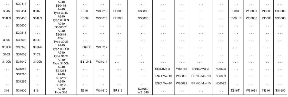
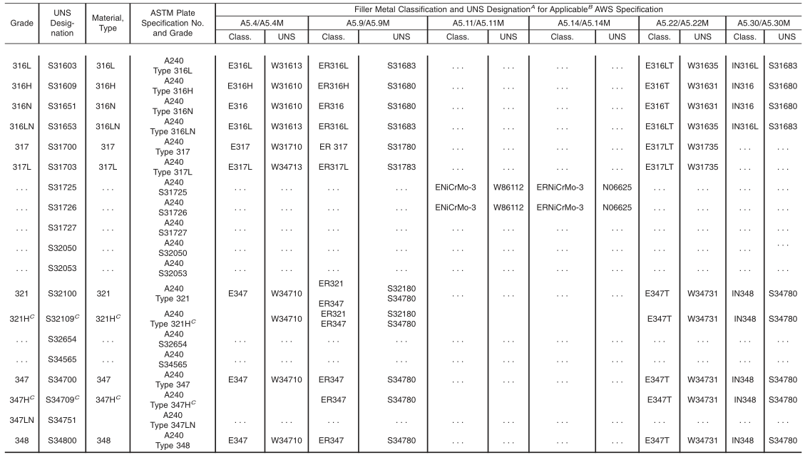
6.1.1 The steel plate material shall conform to the requirements of one of the grades of Specification A240/A240M,listed in Table 1, except as provided in 6.3.2.3.
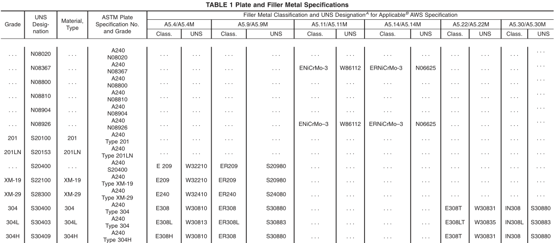
A New designation established in accordance with Practice E527and SAE J1086.
B Choice of American Welding Society specification depends on the welding process used.
C Minimum carbon content of the filler metal shall be 0.040 mass %.
D In previous editions, S30600 was incorrectly shown as S01815.
6.2 Welding:
6.2.1 The joints shall be full penetration double-welded or single-welded butt joints employing fusion welding processes as defined under “Definitions,” ASME Boiler and Pressure Vessel Code, Section IX. This specification makes no provision for any difference in weld quality requirements regardless of the weld joint type employed (single or double) in making the weld. Where backing rings or strips are employed, the ring or strip material shall be of the same P-Number (Table QW-422 of Section IX) as the plate being joined. Backing rings or strips shall be completely removed after welding, prior to any required radiography, and the exposed weld surface shall be examined visually for conformance to the requirements of
6.2.3. Welds made by procedures employing backing strips or rings that remain in place are prohibited. Welding procedures,and welding operators shall be qualified in accordance with ASME Boiler and Pressure Vessel Code, Section IX.
6.2.2 Except as provided in 6.2.2.1 and 6.2.2.2, welds shall be made in their entirety by processes involving the deposition of filler metal.
6.2.2.1 For Class 4 pipe employing multiple passes, the root-pass may be without the addition of filler metal.
6.2.2.2 For Class 4 pipe, the weld surface exposed inside the pipe may result from a single pass made from the inside of the pipe without the addition of filler metal.
6.2.2.3 All single-welded pipe shall be completely radiographed.
6.2.3 The weld surface on either side of the weld is permitted to be flush with the base plate or to have a reasonably uniform crown, not to exceed 1 ⁄ 8 in. [3 mm]. It is permitted at the option of the manufacturer or by agreement between the manufacturer and purchaser to remove any weld reinforcement. The contour of the reinforcement should be reasonably smooth and free from irregularities. The deposited metal shall be fused uniformly into the plate surface. No concavity of contour is permitted unless the resulting thickness of weld metal is equal to or greater than the minimum thickness of the adjacent base metal.
6.2.4 Weld defects shall be repaired by removal to sound metal and rewelding. Subsequent heat treatment and examination (that is, visual, radiographic, and dye penetrant) shall be as required on the original welds.
6.3 Heat Treatment:
6.3.1 Unless otherwise stated in the order, all pipe shall be furnished in the heat-treated condition in accordance with the requirements of Table 2.
A New designation established in accordance with Practice E527 and SAE J1086.
B Minimum, unless otherwise stated.
C Quenched in water or rapidly cooled by other means, at a rate sufficient to prevent reprecipitation of carbides, as demonstrable by the capability of passing Practices A262, Practice E. The manufacturer is not required to run the test unless it is specified on the purchase order (see Supplementary Requirement S7). Note that Practices A262 requires the test to be performed on sensitized specimens in the low-carbon and stabilized types and on specimens representative of the as-shipped condition for other types. In the case of low-carbon types containing 3 % or more molybdenum, the applicability of the sensitizing treatment prior to testing shall be a matter for negotiation between the seller and the purchaser.
D Quenched in water or rapidly cooled by other means.
6.3.2 The purchase order shall specify one of the following conditions if the heat-treated condition specified in 6.3.1 is not desired by the purchaser:
6.3.2.1 A final heat-treatment temperature under 1900 °F [1040 °C]—Each pipe supplied under this requirement shall be stenciled with the final heat-treatment temperature in degrees Fahrenheit or degrees Celsius after the suffix “HT”. Controlled structural or special service characteristics may be specified as a guide for the most suitable heat treatment.
6.3.2.2 No final heat treatment of pipe fabricated of plate that has been solution heat treated at temperatures required by this specification—Each pipe supplied under this requirement shall be stenciled with the suffix “HT-O”.
6.3.2.3 No final heat treatment of pipe fabricated of plate that has not been solution heat treated—Each pipe supplied under this requirement shall be stenciled with the suffix“HT-SO”.
6.4 A solution annealing temperature above 1950 °F [1065°C] may impair the resistance to intergranular corrosion after subsequent exposure to sensitizing conditions in Grades 321,321H, 347, 347H, and 348. When specified by the purchaser, a lower temperature stabilization or re-solution anneal shall be used subsequent to the initial high temperature solution anneal(see Supplementary Requirement S5).
7. Chemical Composition
7.1 The chemical composition of the plate shall conform to the requirements of the applicable specification and grade listed in Specification A240/A240M.
7.2 Except for Grade S34751, the chemical composition of the welding filler metal shall conform to the requirements of the applicable AWS specification for the corresponding grade shown in Table 1, or shall conform to the chemical composition specified for the plate in Specification A240/A240M, or shall, subject to purchaser approval, be a filler metal more highly alloyed than the base metal when needed for corrosion resistance or other properties. Use of a filler metal other than that listed in Table 1 or conforming to the chemical composition specified for the plate in Specification A240/A240M shall be reported and the filler metal identified on the certificate of tests. When nitrogen and cerium are specified elements for the ordered grade, the method of analysis for these elements shall be a matter of agreement between the purchaser and the manufacturer.
7.3 The chemical composition of the welding filler metal for Grade S34751 shall conform to the chemical composition specified for the plate in Specification A240/A240M. The method for analysis for nitrogen shall be a matter of agreement between the purchaser and the manufacturer.
8. Permissible Variations in Dimensions
8.1 Permissible Variations—The dimensions at any point in a length of pipe shall not exceed the following:
8.1.1 Outside Diameter—Based on circumferential measurement, 60.5 % of the specified outside diameter.
8.1.2 Out-of-Roundness—Difference between major and minor outside diameters, 1 %.
8.1.3 Alignment—Using a 10-ft [3-m] straightedge placed so that both ends are in contact with the pipe,1 ⁄ 8 in. [3 mm]deviation from contact with the pipe.
8.1.4 Thickness—The minimum wall thickness at any point in the pipe shall not be more than 0.01 in. [0.3 mm] under the nominal thickness.
9. Workmanship, Finish, and Appearance
9.1 The finished pipe shall have a workmanlike finish.
9.2 Repair of Plate Defects by Machining or Grinding—It is permitted to repair pipes showing slivers, or other surface defects, by machining or grounding inside or outside to a depth that ensures the removal of all included scale and slivers,provided that the wall thickness is not reduced below the specified minimum wall thickness. Machining or grinding shall follow inspection of the pipe as rolled, and shall be followed by supplementary visual inspection.
9.3 Repair of Plate Defects by Welding—It is permitted to repair by welding defects that violate minimum wall thickness,but only with the approval of the purchaser. Areas shall be suitably prepared for welding with tightly closed defects removed by grinding. Open, clean defects, such as pits or impressions, may require no preparation. All welders, welding operators, and weld procedures shall be qualified to the ASME Boiler and Pressure Vessel Code, Section IX. Unless the
purchaser specifies otherwise, pipe required to be heat treated under the provisions of 6.3, shall be heat treated or reheat treated following repair welding. Repaired lengths, where repair depth is greater than
1 ⁄ 4 of the thickness, shall be pressure tested or repressure tested after repair and heat treatment (if any). Repair welds shall also be examined by suitable nondestructive examination techniques, including any techniques specifically required of the primary weld.
9.4 The pipe shall be free of scale and contaminating iron particles. Pickling, blasting, or surface finishing is not mandatory when pipe is bright annealed. The purchaser is permitted to request that a passivating treatment be applied.
10. Heat Analysis
10.1 An analysis of each heat of steel shall be made by the plate manufacturer to determine the percentages of the elements prescribed in Specification A240/A240M. The chemical composition thus determined shall conform to the requirements prescribed in Specification A240/A240M.
11. Product Analysis
11.1 For each lot of 500 ft [150 m] of pipe or fraction thereof, analysis shall be made by the manufacturer from the finished pipe of the plate and of the weld deposit. Drillings for analysis may be taken from the mechanical test specimens. The results of these analyses shall be reported to the purchaser or the purchaser’s representative, and shall conform to the requirements of Section 7, subject to the product analysis tolerances of Table 1 in Specification A480/A480M.
11.2 If the analysis of one of the tests specified in 9.1 does not conform to the requirements specified in Section 7,analyses shall be made on additional pipe of double the original number from the same lot, each of which shall conform to the requirements specified.
12. Tensile Requirements
12.1 The plate used in making the pipe shall conform to the requirements as to tensile properties of the applicable specifications listed in Table 1. Tension tests made by the plate manufacturer shall qualify the plate material.
12.2 The transverse tension test taken across the welded joint specimen shall have a tensile strength not less than the specified minimum tensile strength of the plate.
13. Transverse Guided-Bend Weld Tests
13.1 Two bend test specimens shall be taken transversely from the pipe. Except as provided in 13.2, one shall be subject to a face guided-bend test and the second to a root guided-bend test. One specimen shall be bent with the inside surface of the pipe against the plunger, and the other with the outside surface against the plunger.
13.2 For wall thicknesses over 3 ⁄ 8 in. [9.5 mm] but less than 3 ⁄ 4 in. [19 mm] side-bend tests may be made instead of the face and root-bend tests. For specified wall thicknesses 3 ⁄ 4 in. [19mm] and over, both specimens shall be subjected to the side-bend tests. Side-bend specimens shall be bent so that one of the side surfaces becomes the convex surface of the bend specimen.
13.3 The bend test shall be acceptable if no cracks or other defects exceeding 1 ⁄ 8 in. [3 mm] in any direction is present in the weld metal or between the weld and the pipe metal after bending. Cracks that originate along the edges of the specimen during testing, and that are less than 1 ⁄ 4 in. [6.5 mm] measured in any direction shall not be considered.
14. Test Specimens and Methods of Testing
14.1 Transverse tension and bend test specimens shall be taken from the end of the finished pipe; the transverse tension and bend test specimens shall be flattened cold before final machining to size.
14.2 As an alternative to the requirements of 14.1, it is permitted to take the test specimens from a test plate of the same material as the pipe that is attached to the end of the cylinder and welded as a prolongation of the pipe longitudinal seam.
14.3 Tension test specimens shall be made in accordance with Section IX, Part QW, Paragraph QW-150 of the ASME Boiler and Pressure Vessel Code and shall be one of the types shown in QW-462.1 of that code.
14.3.1 Reduced-section specimens conforming to the requirements given in QW-462.1(b) may be used for tension tests on all thicknesses of pipe having outside diameter greater than 3 in. [76 mm].
14.3.2 Turned specimens conforming to the requirements of QW-462.1(d) may be used for tension tests.
14.3.2.1 If turned specimens are used as given in 14.3.2.2 and 14.3.2.3, one complete set shall be made for each required tension test.
14.3.2.2 For thicknesses to and including 1 1 ⁄ 4 in. [32 mm], it is permitted to use a single turned specimen.
14.3.2.3 For thicknesses over 1 1 ⁄ 4 in. [32 mm], multiple specimens shall be cut through the full thickness of the weld with their centers parallel to the material surface and not over 1 in. [25 mm] apart. The centers of the specimens adjacent to material surfaces shall not exceed 5 ⁄ 8in.[16 mm] from the surface.
14.4 The test specimens shall not be cut from the pipe or test plate until after final heat treatment.
15. Mechanical Tests Required
15.1 For the purposes of the tension and bend test requirements, the term “lot” shall mean all pipe of the same grade, permitted to include more that one heat of steel, within a 3 ⁄ 16 -in [4.7-mm] range of thickness and welded to the same weld procedure, and when heat treated, done so to the same heat-treating procedure and in the same furnace. The maximum lot size shall be 200 linear ft [60 m] of pipe.
15.1.1 Transverse Tension Test—One test shall be made to represent each lot of finished pipe.
15.1.2 Transverse Guided-Bend Weld Test—One test (two specimens) shall be made to represent each lot of finished pipe.
15.2 Hydrostatic Test—Each length of pipe shall be subjected to a hydrostatic test in accordance with Specification A999/A999M, unless specifically exempted under the provision of 15.3. Pressure shall be held for a sufficient time to permit the inspector to examine the entire length of the welded seam.
15.3 The purchaser, with the agreement of the manufacturer,is permitted to complete the hydrostatic test requirement with the system pressure test, performed at a pressure either lower or higher than the specification test pressure, but in no case shall the test pressure be lower than the system design pressure.Each length of pipe furnished without the completed manufacturer’s hydrostatic test shall include with the mandatory marking the letters “NH.”
16. Radiographic Examination
16.1 For Classes 1, 3, and 4 pipe, all welded joints shall be completely examined by radiography.
16.2 For Class 5 pipe, the welded joints shall be spot radiographed to the extent of not less than 12 in. [300 mm] of radiograph per 50 ft [15 m] of weld.
16.3 For Classes 1, 3, and 4 pipe, radiographic examination shall be in accordance with the requirements of the ASME Boiler and Pressure Vessel Code, Section VIII, latest edition,Paragraph UW-51.
16.4 For Class 5 pipe, radiographic examination shall be in accordance with the requirements of the ASME Boiler and Pressure Vessel Code, Section VIII, Division 1, latest edition,Paragraph UW-52.
16.5 Radiographic examination is permitted to be performed prior to heat treatment.
17. Lengths
17.1 Circumferentially welded joints of the same quality as the longitudinal joints shall be permitted by agreement between the manufacturer and the purchaser.
18. Product Marking
18.1 In addition to the marking prescribed in Specification A999/A999M, the markings on each length of pipe shall include the plate material designations as shown in Table 1, the marking requirements of 6.3 and 15.3, and Class 1, 2, 3, or 4,as appropriate (see 1.3).
18.2 Bar Coding—In addition to the requirements in 18.1,bar coding is acceptable as a supplementary identification method. Bar coding should be consistent with the Automotive Industry Action Group (AIAG) standard prepared by the Primary Metals Subcommittee of the AIAG Bar Code Project Team.
19. Keywords
19.1 arc welded steel pipe; austenitic stainless steel;chromium-nickel steel; fusion welded steel pipe; high temperature application; steel pipe; temperature service applications;high; welded steel pipe
Standard Specification for Electric-Fusion-Welded Austenitic Chromium-Nickel Stainless Steel Pipe for High-Temperature Service and General Applications
1. Scope*
1.1 This specification covers electric-fusion-welded austenitic chromium-nickel stainless steel pipe suitable for corrosive or high-temperature service, or both, or for general applications.
NOTE 1—The dimensionless designator NPS (nominal pipe size) has been substituted in this standard for such traditional terms as “nominal diameter,” “size,” and “nominal size.”
1.2 This specification covers the grades of alloy and stainless steel listed in Table 1. The selection of the proper grade and requirements for heat treatment shall be at the discretion of the purchaser,dependent on the service conditions to be encountered.
1.3 Five classes of pipe are covered as follows:
1.3.1 Class 1—Pipe shall be double welded by processes employing filler metal in all passes and shall be completely radiographed.
1.3.2 Class 2—Pipe shall be double welded by processes employing filler metal in all passes. No radiography is required.
1.3.3 Class 3—Pipe shall be single welded by processes employing filler metal in all passes and shall be completely radiographed.
1.3.4 Class 4—Same as Class 3 except that the weld pass exposed to the inside pipe surface may be made without the addition of filler metal (see 6.2.2.1 and 6.2.2.2).
1.3.5 Class 5—Pipe shall be double welded by processes employing filler metal in all passes and shall be spot radiographed.
1.4 Supplementary requirements covering provisions ranging from additional testing to formalized procedures for manufacturing practice are provided. Supplementary Requirements S1 through S6 are included as options to be specified when desired.
1.5 The values stated in either inch-pound units or SI units are to be regarded separately as standard. Within the text, the SI units are shown in brackets. The values stated in each system may not be exact equivalents; therefore, each system shall be used independently of the other. Combining values from the two systems may result in nonconformance with the specification. The inch-pound units shall apply unless the “M”designation of this specification is specified in the order.
2. Referenced Documents
2.1 ASTM Standards:
A240/A240M Specification for Chromium and Chromium-Nickel Stainless Steel Plate, Sheet, and Strip for Pressure Vessels and for General Applications
A262 Practices for Detecting Susceptibility to Intergranular Attack in Austenitic Stainless Steels
A480/A480M Specification for General Requirements for Flat-Rolled Stainless and Heat-Resisting Steel Plate,Sheet, and Strip
A941 Terminology Relating to Steel, Stainless Steel, Related Alloys, and Ferroalloys
A999/A999M Specification for General Requirements for Alloy and Stainless Steel Pipe
E527 Practice for Numbering Metals and Alloys in the Unified Numbering System (UNS)
2.2 ASME Boiler and Pressure Vessel Code:
Section II, Materials
Section III, Rules for Construction of Nuclear Facility Components
Section VIII, Rules for Construction of Pressure Vessels
Section IX, Welding and Brazing Qualifications
2.3 AWS Specifications:
A5.4/A5.4M Stainless Steel Electrodes for Shielded Metal Arc Welding
A5.9/A5.9M Bare Stainless Steel Welding Electrodes and Rods
A5.11/A5.11M Nickel and Nickel-Alloy Welding Electrodes for Shielded Metal Arc Welding
A5.14/A5.14M Nickel and Nickel-Alloy Bare Welding Electrodes and Rods
A5.22/A5.22M Stainless Steel Flux Cored and Metal Cored Welding Electrodes and Rods
A5.30/A5.30M Consumable Inserts
2.4 Other Standard:
SAE J1086 Practice for Numbering Metals and Alloys(UNS)
3. Terminology
3.1 Definitions:
3.1.1 The definitions in Specification A999/A999M and Terminology A941 are applicable to this specification.
4. Ordering Information
4.1 It shall be the responsibility of the purchaser to specify all requirements that are necessary for product under this specification. Such requirements to be considered include, but are not limited to, the following:
4.1.1 Quantity (feet, metres, or number of lengths),
4.1.2 Name of material (electric-fusion-welded pipe),
4.1.3 Grade (Table 1),
4.1.4 Class (see 1.3),
4.1.5 Size (outside diameter and nominal wall thickness),
4.1.6 Length (specific or random),
4.1.7 End finish (Section on Ends of Specification A999/A999M),
4.1.8 Authorization for repair of plate defects by welding and subsequent heat treatment without prior approval if such is intended(see 9.3),
4.1.9 Specification designation,
4.1.10 Special requirements,
4.1.11 Statement invoking requirements of 16.4 if such is intended.
4.1.12 Circumferential weld permissibility (see Section 16),
4.1.13 Supplementary Requirements (S1 through S8),
4.1.14 Applicable ASME Code if known,
4.1.15 For ASME Code Section III applications, the service classification intended, and
4.1.16 Certification requirements (see Section on Certification of Specification A999/A999M).
5. General Requirements
5.1 Material furnished to this specification shall conform to the applicable requirements of the current edition of Specification A999/A999M unless otherwise provided herein.
6. Materials and Manufacture
6.1 Materials:
6.1.1 The steel plate material shall conform to the requirements of one of the grades of Specification A240/A240M,listed in Table 1, except as provided in 6.3.2.3.
TABLE 1 Plate and Filler Metal Specifications
TABLE 1 Continued
A New designation established in accordance with Practice E527and SAE J1086.
B Choice of American Welding Society specification depends on the welding process used.
C Minimum carbon content of the filler metal shall be 0.040 mass %.
D In previous editions, S30600 was incorrectly shown as S01815.
6.2 Welding:
6.2.1 The joints shall be full penetration double-welded or single-welded butt joints employing fusion welding processes as defined under “Definitions,” ASME Boiler and Pressure Vessel Code, Section IX. This specification makes no provision for any difference in weld quality requirements regardless of the weld joint type employed (single or double) in making the weld. Where backing rings or strips are employed, the ring or strip material shall be of the same P-Number (Table QW-422 of Section IX) as the plate being joined. Backing rings or strips shall be completely removed after welding, prior to any required radiography, and the exposed weld surface shall be examined visually for conformance to the requirements of
6.2.3. Welds made by procedures employing backing strips or rings that remain in place are prohibited. Welding procedures,and welding operators shall be qualified in accordance with ASME Boiler and Pressure Vessel Code, Section IX.
6.2.2 Except as provided in 6.2.2.1 and 6.2.2.2, welds shall be made in their entirety by processes involving the deposition of filler metal.
6.2.2.1 For Class 4 pipe employing multiple passes, the root-pass may be without the addition of filler metal.
6.2.2.2 For Class 4 pipe, the weld surface exposed inside the pipe may result from a single pass made from the inside of the pipe without the addition of filler metal.
6.2.2.3 All single-welded pipe shall be completely radiographed.
6.2.3 The weld surface on either side of the weld is permitted to be flush with the base plate or to have a reasonably uniform crown, not to exceed 1 ⁄ 8 in. [3 mm]. It is permitted at the option of the manufacturer or by agreement between the manufacturer and purchaser to remove any weld reinforcement. The contour of the reinforcement should be reasonably smooth and free from irregularities. The deposited metal shall be fused uniformly into the plate surface. No concavity of contour is permitted unless the resulting thickness of weld metal is equal to or greater than the minimum thickness of the adjacent base metal.
6.2.4 Weld defects shall be repaired by removal to sound metal and rewelding. Subsequent heat treatment and examination (that is, visual, radiographic, and dye penetrant) shall be as required on the original welds.
6.3 Heat Treatment:
6.3.1 Unless otherwise stated in the order, all pipe shall be furnished in the heat-treated condition in accordance with the requirements of Table 2.
TABLE 2 Annealing Requirements
| Grade or UNS Designation A |
Heat Treating Temperature B |
Cooling/Testing Requirements |
| All grades not individually listed below: | 1900 °F [1040 °C] | C |
| 304H, 309S, 309Cb, 310S, 310Cb,321H, 347H, S22100, S28300, | 1900 °F [1040 °C] | D |
| N08020 | 1800-1850 °F [980-1010 °C] | D |
| N08367 | 2025 °F [1110 °C] | D |
| N08810 | 2050 °F [1120 °C] | D |
| N08904 | 2000 °F [1095 °C] | D |
| N08926 | 2010 °F [1100 °C] | D |
| S30600 | 2100 °F [1150 °C] | D |
| S30815 | 1920 °F [1050 °C] | D |
| S31254 | 2100 °F [1150 °C] | D |
| S31266 | 2100 °F [1150 °C] | D |
| S31727 | 1975–2175 °F [1080 to 1180 °C] | D |
| S32050 | 2100 °F [1150 °C] | D |
| S32053 | 1975–2175 °F [1080 to 1180 °C] | D |
| S32654 | 2100 °F [1150 °C] | D |
| S34565 | 2050 °F [1120 °C] | D |
A New designation established in accordance with Practice E527 and SAE J1086.
B Minimum, unless otherwise stated.
C Quenched in water or rapidly cooled by other means, at a rate sufficient to prevent reprecipitation of carbides, as demonstrable by the capability of passing Practices A262, Practice E. The manufacturer is not required to run the test unless it is specified on the purchase order (see Supplementary Requirement S7). Note that Practices A262 requires the test to be performed on sensitized specimens in the low-carbon and stabilized types and on specimens representative of the as-shipped condition for other types. In the case of low-carbon types containing 3 % or more molybdenum, the applicability of the sensitizing treatment prior to testing shall be a matter for negotiation between the seller and the purchaser.
D Quenched in water or rapidly cooled by other means.
6.3.2 The purchase order shall specify one of the following conditions if the heat-treated condition specified in 6.3.1 is not desired by the purchaser:
6.3.2.1 A final heat-treatment temperature under 1900 °F [1040 °C]—Each pipe supplied under this requirement shall be stenciled with the final heat-treatment temperature in degrees Fahrenheit or degrees Celsius after the suffix “HT”. Controlled structural or special service characteristics may be specified as a guide for the most suitable heat treatment.
6.3.2.2 No final heat treatment of pipe fabricated of plate that has been solution heat treated at temperatures required by this specification—Each pipe supplied under this requirement shall be stenciled with the suffix “HT-O”.
6.3.2.3 No final heat treatment of pipe fabricated of plate that has not been solution heat treated—Each pipe supplied under this requirement shall be stenciled with the suffix“HT-SO”.
6.4 A solution annealing temperature above 1950 °F [1065°C] may impair the resistance to intergranular corrosion after subsequent exposure to sensitizing conditions in Grades 321,321H, 347, 347H, and 348. When specified by the purchaser, a lower temperature stabilization or re-solution anneal shall be used subsequent to the initial high temperature solution anneal(see Supplementary Requirement S5).
7. Chemical Composition
7.1 The chemical composition of the plate shall conform to the requirements of the applicable specification and grade listed in Specification A240/A240M.
7.2 Except for Grade S34751, the chemical composition of the welding filler metal shall conform to the requirements of the applicable AWS specification for the corresponding grade shown in Table 1, or shall conform to the chemical composition specified for the plate in Specification A240/A240M, or shall, subject to purchaser approval, be a filler metal more highly alloyed than the base metal when needed for corrosion resistance or other properties. Use of a filler metal other than that listed in Table 1 or conforming to the chemical composition specified for the plate in Specification A240/A240M shall be reported and the filler metal identified on the certificate of tests. When nitrogen and cerium are specified elements for the ordered grade, the method of analysis for these elements shall be a matter of agreement between the purchaser and the manufacturer.
7.3 The chemical composition of the welding filler metal for Grade S34751 shall conform to the chemical composition specified for the plate in Specification A240/A240M. The method for analysis for nitrogen shall be a matter of agreement between the purchaser and the manufacturer.
8. Permissible Variations in Dimensions
8.1 Permissible Variations—The dimensions at any point in a length of pipe shall not exceed the following:
8.1.1 Outside Diameter—Based on circumferential measurement, 60.5 % of the specified outside diameter.
8.1.2 Out-of-Roundness—Difference between major and minor outside diameters, 1 %.
8.1.3 Alignment—Using a 10-ft [3-m] straightedge placed so that both ends are in contact with the pipe,1 ⁄ 8 in. [3 mm]deviation from contact with the pipe.
8.1.4 Thickness—The minimum wall thickness at any point in the pipe shall not be more than 0.01 in. [0.3 mm] under the nominal thickness.
9. Workmanship, Finish, and Appearance
9.1 The finished pipe shall have a workmanlike finish.
9.2 Repair of Plate Defects by Machining or Grinding—It is permitted to repair pipes showing slivers, or other surface defects, by machining or grounding inside or outside to a depth that ensures the removal of all included scale and slivers,provided that the wall thickness is not reduced below the specified minimum wall thickness. Machining or grinding shall follow inspection of the pipe as rolled, and shall be followed by supplementary visual inspection.
9.3 Repair of Plate Defects by Welding—It is permitted to repair by welding defects that violate minimum wall thickness,but only with the approval of the purchaser. Areas shall be suitably prepared for welding with tightly closed defects removed by grinding. Open, clean defects, such as pits or impressions, may require no preparation. All welders, welding operators, and weld procedures shall be qualified to the ASME Boiler and Pressure Vessel Code, Section IX. Unless the
purchaser specifies otherwise, pipe required to be heat treated under the provisions of 6.3, shall be heat treated or reheat treated following repair welding. Repaired lengths, where repair depth is greater than
1 ⁄ 4 of the thickness, shall be pressure tested or repressure tested after repair and heat treatment (if any). Repair welds shall also be examined by suitable nondestructive examination techniques, including any techniques specifically required of the primary weld.
9.4 The pipe shall be free of scale and contaminating iron particles. Pickling, blasting, or surface finishing is not mandatory when pipe is bright annealed. The purchaser is permitted to request that a passivating treatment be applied.
10. Heat Analysis
10.1 An analysis of each heat of steel shall be made by the plate manufacturer to determine the percentages of the elements prescribed in Specification A240/A240M. The chemical composition thus determined shall conform to the requirements prescribed in Specification A240/A240M.
11. Product Analysis
11.1 For each lot of 500 ft [150 m] of pipe or fraction thereof, analysis shall be made by the manufacturer from the finished pipe of the plate and of the weld deposit. Drillings for analysis may be taken from the mechanical test specimens. The results of these analyses shall be reported to the purchaser or the purchaser’s representative, and shall conform to the requirements of Section 7, subject to the product analysis tolerances of Table 1 in Specification A480/A480M.
11.2 If the analysis of one of the tests specified in 9.1 does not conform to the requirements specified in Section 7,analyses shall be made on additional pipe of double the original number from the same lot, each of which shall conform to the requirements specified.
12. Tensile Requirements
12.1 The plate used in making the pipe shall conform to the requirements as to tensile properties of the applicable specifications listed in Table 1. Tension tests made by the plate manufacturer shall qualify the plate material.
12.2 The transverse tension test taken across the welded joint specimen shall have a tensile strength not less than the specified minimum tensile strength of the plate.
13. Transverse Guided-Bend Weld Tests
13.1 Two bend test specimens shall be taken transversely from the pipe. Except as provided in 13.2, one shall be subject to a face guided-bend test and the second to a root guided-bend test. One specimen shall be bent with the inside surface of the pipe against the plunger, and the other with the outside surface against the plunger.
13.2 For wall thicknesses over 3 ⁄ 8 in. [9.5 mm] but less than 3 ⁄ 4 in. [19 mm] side-bend tests may be made instead of the face and root-bend tests. For specified wall thicknesses 3 ⁄ 4 in. [19mm] and over, both specimens shall be subjected to the side-bend tests. Side-bend specimens shall be bent so that one of the side surfaces becomes the convex surface of the bend specimen.
13.3 The bend test shall be acceptable if no cracks or other defects exceeding 1 ⁄ 8 in. [3 mm] in any direction is present in the weld metal or between the weld and the pipe metal after bending. Cracks that originate along the edges of the specimen during testing, and that are less than 1 ⁄ 4 in. [6.5 mm] measured in any direction shall not be considered.
14. Test Specimens and Methods of Testing
14.1 Transverse tension and bend test specimens shall be taken from the end of the finished pipe; the transverse tension and bend test specimens shall be flattened cold before final machining to size.
14.2 As an alternative to the requirements of 14.1, it is permitted to take the test specimens from a test plate of the same material as the pipe that is attached to the end of the cylinder and welded as a prolongation of the pipe longitudinal seam.
14.3 Tension test specimens shall be made in accordance with Section IX, Part QW, Paragraph QW-150 of the ASME Boiler and Pressure Vessel Code and shall be one of the types shown in QW-462.1 of that code.
14.3.1 Reduced-section specimens conforming to the requirements given in QW-462.1(b) may be used for tension tests on all thicknesses of pipe having outside diameter greater than 3 in. [76 mm].
14.3.2 Turned specimens conforming to the requirements of QW-462.1(d) may be used for tension tests.
14.3.2.1 If turned specimens are used as given in 14.3.2.2 and 14.3.2.3, one complete set shall be made for each required tension test.
14.3.2.2 For thicknesses to and including 1 1 ⁄ 4 in. [32 mm], it is permitted to use a single turned specimen.
14.3.2.3 For thicknesses over 1 1 ⁄ 4 in. [32 mm], multiple specimens shall be cut through the full thickness of the weld with their centers parallel to the material surface and not over 1 in. [25 mm] apart. The centers of the specimens adjacent to material surfaces shall not exceed 5 ⁄ 8in.[16 mm] from the surface.
14.4 The test specimens shall not be cut from the pipe or test plate until after final heat treatment.
15. Mechanical Tests Required
15.1 For the purposes of the tension and bend test requirements, the term “lot” shall mean all pipe of the same grade, permitted to include more that one heat of steel, within a 3 ⁄ 16 -in [4.7-mm] range of thickness and welded to the same weld procedure, and when heat treated, done so to the same heat-treating procedure and in the same furnace. The maximum lot size shall be 200 linear ft [60 m] of pipe.
15.1.1 Transverse Tension Test—One test shall be made to represent each lot of finished pipe.
15.1.2 Transverse Guided-Bend Weld Test—One test (two specimens) shall be made to represent each lot of finished pipe.
15.2 Hydrostatic Test—Each length of pipe shall be subjected to a hydrostatic test in accordance with Specification A999/A999M, unless specifically exempted under the provision of 15.3. Pressure shall be held for a sufficient time to permit the inspector to examine the entire length of the welded seam.
15.3 The purchaser, with the agreement of the manufacturer,is permitted to complete the hydrostatic test requirement with the system pressure test, performed at a pressure either lower or higher than the specification test pressure, but in no case shall the test pressure be lower than the system design pressure.Each length of pipe furnished without the completed manufacturer’s hydrostatic test shall include with the mandatory marking the letters “NH.”
16. Radiographic Examination
16.1 For Classes 1, 3, and 4 pipe, all welded joints shall be completely examined by radiography.
16.2 For Class 5 pipe, the welded joints shall be spot radiographed to the extent of not less than 12 in. [300 mm] of radiograph per 50 ft [15 m] of weld.
16.3 For Classes 1, 3, and 4 pipe, radiographic examination shall be in accordance with the requirements of the ASME Boiler and Pressure Vessel Code, Section VIII, latest edition,Paragraph UW-51.
16.4 For Class 5 pipe, radiographic examination shall be in accordance with the requirements of the ASME Boiler and Pressure Vessel Code, Section VIII, Division 1, latest edition,Paragraph UW-52.
16.5 Radiographic examination is permitted to be performed prior to heat treatment.
17. Lengths
17.1 Circumferentially welded joints of the same quality as the longitudinal joints shall be permitted by agreement between the manufacturer and the purchaser.
18. Product Marking
18.1 In addition to the marking prescribed in Specification A999/A999M, the markings on each length of pipe shall include the plate material designations as shown in Table 1, the marking requirements of 6.3 and 15.3, and Class 1, 2, 3, or 4,as appropriate (see 1.3).
18.2 Bar Coding—In addition to the requirements in 18.1,bar coding is acceptable as a supplementary identification method. Bar coding should be consistent with the Automotive Industry Action Group (AIAG) standard prepared by the Primary Metals Subcommittee of the AIAG Bar Code Project Team.
19. Keywords
19.1 arc welded steel pipe; austenitic stainless steel;chromium-nickel steel; fusion welded steel pipe; high temperature application; steel pipe; temperature service applications;high; welded steel pipe